Alarm Control
High sensitivity anti-theft alarm circuit with high loudness
Published:2012/12/2 21:28:00 Author:Ecco | Keyword: High sensitivity, anti-theft alarm, high loudness | From:SeekIC
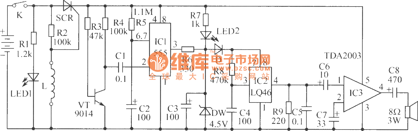
The SCR, R2 and L form a triggered power switch with controllable disconnection, L is an anti-theft wire. Transistor VT and IC1 form approximately 2min monostable delay trigger circuit. IC2 is the language alarm circuit which can emit the sound of catch thief, please . Usually when K is closed, if there is no thief, the alarm burglar lines will make SCR control gate trigger current be short, SCR is off, the circuit does not work, and it is in the probation status. If thied jumps over the wall of park, the wire L is pulled and disconnected, SCR control pole gets triggered current by R2, then it is be turned on to provide the power for working circuit.
Reprinted Url Of This Article:
http://www.seekic.com/circuit_diagram/Control_Circuit/Alarm_Control/High_sensitivity_anti_theft_alarm_circuit_with_high_loudness.html
Print this Page | Comments | Reading(3)

Article Categories
power supply circuit
Amplifier Circuit
Basic Circuit
LED and Light Circuit
Sensor Circuit
Signal Processing
Electrical Equipment Circuit
Control Circuit
Remote Control Circuit
A/D-D/A Converter Circuit
Audio Circuit
Measuring and Test Circuit
Communication Circuit
Computer-Related Circuit
555 Circuit
Automotive Circuit
Repairing Circuit
Code: