Alarm Control
Four-sound circulating burglar alarm circuit
Published:2011/10/27 21:52:00 Author:May | Keyword: Four-sound circulating, burglar alarm | From:SeekIC

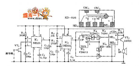
When field-effect tube VT1 (3DJ6)'s wire is serviceable, it presents cut-off state, andpin 2 of JG (555) setting trigger end presents high level, and 555 is in reset state, namely pin 3 presents low level ( it islower than 0.4V). 555 and R1, C1 form the monostable trigger circuit. Whenpeople touch wire, human body's induction signal is amplified byVT1,set byIC1, thenits pin 3 turns to high level ( about 6V) to offer work voltage to IC2, VT2, etc.
When the wire is broken, IC1 is always in setting state, IC2, IC6, etc get electricity to be in continuous alarm state, and it send sout four- sound circulating alarm sound. IC2 and R2, R3, C4, etc make up ultra-low frequency multivibrator, and the oscillation or not depends on thepower supply. Its oscillation frequency f=1.44/(R2+2R3)C4.
Reprinted Url Of This Article:
http://www.seekic.com/circuit_diagram/Control_Circuit/Alarm_Control/Four_sound_circulating_burglar_alarm_circuit.html
Print this Page | Comments | Reading(3)

Article Categories
power supply circuit
Amplifier Circuit
Basic Circuit
LED and Light Circuit
Sensor Circuit
Signal Processing
Electrical Equipment Circuit
Control Circuit
Remote Control Circuit
A/D-D/A Converter Circuit
Audio Circuit
Measuring and Test Circuit
Communication Circuit
Computer-Related Circuit
555 Circuit
Automotive Circuit
Repairing Circuit
Code: