Control Circuit
555 sound and light synchronous touch-bell metronome circuit
Published:2011/6/15 8:57:00 Author:TaoXi | Keyword: 555, sound, light, synchronous touch-bell, metronome | From:SeekIC

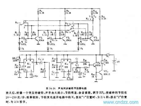
As the figure 14-34 shows, the metronome is composed of two beat generators, the bell sound amplification circuit and the luminous display circuit.
The multivibrators is composed of the IC1, RP1, R14, C4 and the IC2, R16, R17, C6 respectively, the oscillation frequency of IC1 is f1=1.44/(RP1+2R14)C4, it is in the range of 1Hz~100Hz. The oscillation frequency of IC2 is f2=1.44/(R16+2R17)C6, it is about 1000Hz. The duty ratio of IC1's oscillation square-wave can be very large, if the resistance of RP1 is 100kΩ, f1 is about 2Hz, the duty ratio is about 99%.
The oscillation square-wave which is output by the IC2 adds to VT4 through C7 and R18. When the positive differential pulse of IC1 comes, the two channels of signals act on VT4 at the same time to make the jet current of VT4 very large.
Reprinted Url Of This Article:
http://www.seekic.com/circuit_diagram/Control_Circuit/555_sound_and_light_synchronous_touch_bell_metronome_circuit.html
Print this Page | Comments | Reading(3)

Article Categories
power supply circuit
Amplifier Circuit
Basic Circuit
LED and Light Circuit
Sensor Circuit
Signal Processing
Electrical Equipment Circuit
Control Circuit
Remote Control Circuit
A/D-D/A Converter Circuit
Audio Circuit
Measuring and Test Circuit
Communication Circuit
Computer-Related Circuit
555 Circuit
Automotive Circuit
Repairing Circuit
Code: