Control Circuit
555 sound and light signal metronome circuit
Published:2011/6/15 8:38:00 Author:TaoXi | Keyword: 555, sound, light, signal, metronome | From:SeekIC

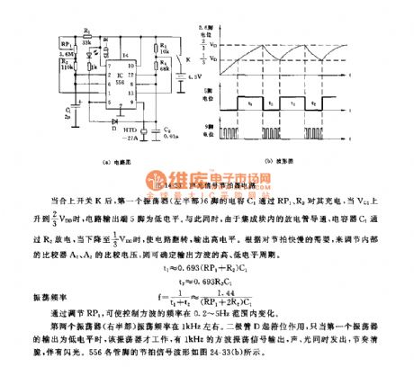
As the figure 14-33 shows, this circuit is composed of a pair of time base circuit 556, and the two time base circuits are connected into two multivibrators. One multivibrator is used to produce the 1kHz oscillation square-wave, this oscillation square-wave is output from pin-9 to encourage the piezoelectric ceramics to send out the sound. Another multivibrator is used to produce the low frequency square-wave to modulate the 1kHz square-wave signal.
After the switch K is closed, pin-6's capacitance C1 of the first oscillator charges it through RP1, when the voltage of VC1 is 2/3VDD, the circuit's output port pin-5 has the low electrical level. At the same time, because the disrharge tube of the integrated block is conducted, so the capacitor C1 charges through R2, when the voltage of C1 is 1/3VDD, the circuit turns to output the high electrical level.
Reprinted Url Of This Article:
http://www.seekic.com/circuit_diagram/Control_Circuit/555_sound_and_light_signal_metronome_circuit.html
Print this Page | Comments | Reading(3)

Article Categories
power supply circuit
Amplifier Circuit
Basic Circuit
LED and Light Circuit
Sensor Circuit
Signal Processing
Electrical Equipment Circuit
Control Circuit
Remote Control Circuit
A/D-D/A Converter Circuit
Audio Circuit
Measuring and Test Circuit
Communication Circuit
Computer-Related Circuit
555 Circuit
Automotive Circuit
Repairing Circuit
Code: