Control Circuit
555 music color light controller circuit
Published:2011/5/22 20:27:00 Author:TaoXi | Keyword: music, color light, controller | From:SeekIC
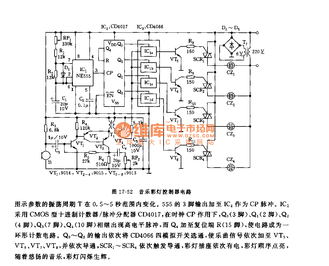
As the figure 17-52 shows, the controller is composed of the acousto-electric conversion circuit, the amplifier circuit, the clock pulse generator, the counter circuit and the control circuit. It controls the 4 channels of color lights to flash with the music.
The pickup microphone changes the music sound into the electric signal, and this signal adds to the 4 channels of analog switch IC3(CD4066). The astable multivibrator is composed of the 555 and RP1,R1,R2,D1,C1.
The parameters' oscillation period T is between 0.5~5 seconds. Pin-3's output of the 555 adds to IC2 as the CP pulse. IC2 uses the CMOS type decimal counter/pulse divider CD4017.
Reprinted Url Of This Article:
http://www.seekic.com/circuit_diagram/Control_Circuit/555_music_color_light_controller_circuit.html
Print this Page | Comments | Reading(3)

Article Categories
power supply circuit
Amplifier Circuit
Basic Circuit
LED and Light Circuit
Sensor Circuit
Signal Processing
Electrical Equipment Circuit
Control Circuit
Remote Control Circuit
A/D-D/A Converter Circuit
Audio Circuit
Measuring and Test Circuit
Communication Circuit
Computer-Related Circuit
555 Circuit
Automotive Circuit
Repairing Circuit
Code: