Control Circuit
555 (TLC555) Relay Driver Circuit
Published:2013/10/21 20:33:00 Author:lynne | Keyword: Relay Driver Circuit | From:SeekIC

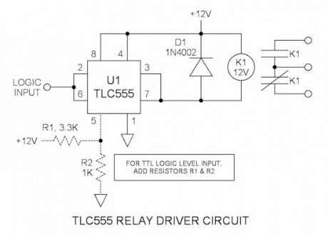
Many integrated circuits have undocumented features or abilities. This is one of them. The TLC555 output (pin 3) can sink a 100mA load to 1.28V. The open drain transistor reset (pin 7) can sink 100mA to 1V. Tying both lines together is permissible because they are logically the same polarity and this potentially doubles the sink current ability to 200mA. This is ideal for driving my 133mA relay coil.The input also has the undocumented, but better known, feature of a Schmitt trigger that provides positive switching.
555 Relay Driver Schematic
Output current rating (pin 3): TLC555 vs. NE555
(Vcc = 15V)
TLC555
NE555
Source current
10mA
200mA
Source mode saturation voltage
Vcc-0.8V
Vcc-2.5V
Sink current
100mA
200mA
Sink mode saturation voltage
1.28V
2.5V
While it can be seen that the NE555 has the higher current rating, its saturation voltage is grossly inferior and this is a detriment in driving loads without excessive voltage drop. Also it can be seen that the TLC555 is much like TTL in that its sourcing ability is far less than its sinking ability. However for driving a relay, we are interested only in current sinking properties.
Reprinted Url Of This Article:
http://www.seekic.com/circuit_diagram/Control_Circuit/555_TLC555_Relay_Driver_Circuit.html
Print this Page | Comments | Reading(3)

Article Categories
power supply circuit
Amplifier Circuit
Basic Circuit
LED and Light Circuit
Sensor Circuit
Signal Processing
Electrical Equipment Circuit
Control Circuit
Remote Control Circuit
A/D-D/A Converter Circuit
Audio Circuit
Measuring and Test Circuit
Communication Circuit
Computer-Related Circuit
555 Circuit
Automotive Circuit
Repairing Circuit
Code: