
Computer-Related Circuit
Index 20
High-precision Constant Current Source Circuit Consisting of TL431
Published:2011/9/3 10:20:00 Author:Zoey | Keyword: High-precision, Constant Current Source
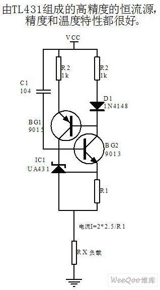
High-precision constant current source circuit consisting of TL431 has an excellent precision and temperature characteristics. (View)
View full Circuit Diagram | Comments | Reading(9018)
TDA1075E microcomputer dialing IC diagram
Published:2011/8/22 2:39:00 Author:Ecco | Keyword: microcomputer dialing IC
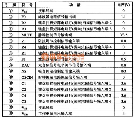
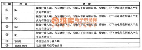
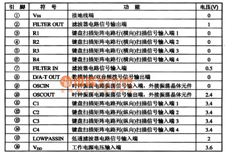
TDA1075E dialing integrated circuit microcomputer system is used in communications equipment for two-tone dialing. TDA1075E integrated circuit includes dual audio dialing generation and key switch codec, mute and other circuits. The IC uses the 18-pin dual in-line package, and the integrated circuit pin functions and data are listed in Table 1-1.
(View)
View full Circuit Diagram | Comments | Reading(821)
TP509 (A) / TP5094 (A) micro-computer dial-up integrated circuit diagram
Published:2011/8/24 21:58:00 Author:Ecco | Keyword: micro-computer, dial-up integrated circuit

TP5092, TP5092A, TP5094, TP5094A are the micro-computer dial-up integrated circuits produced by TEXAS company, and they are used in communication equipment for two-tone dialing. T5092, TP5092A, TP5094, TP5094A integrated circuits contain two-tone hair number generating circuit and key switch encoding and decoding circuit, and they use 16-pin dual in-line package, and the integrated circuit pin functions are listed in Table 1-1.
(View)
View full Circuit Diagram | Comments | Reading(757)
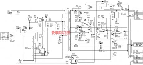
SONY G3F-K Power Supply Circuit-2
Published:2011/8/11 5:44:00 Author:Sue | Keyword: Power Supply
View full Circuit Diagram | Comments | Reading(1299)
The NISSAN new Teana stereo (with GPS) circuit
Published:2011/8/11 3:45:00 Author:Borg | Keyword: NISSAN, Teana, GPS
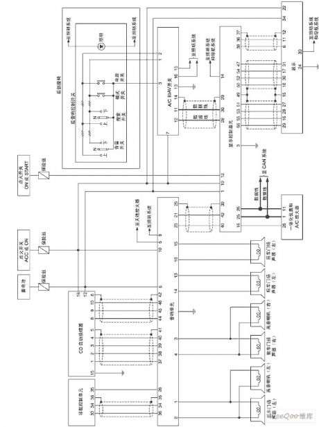
The NISSAN new Teana stereo (with GPS) circuit (View)
View full Circuit Diagram | Comments | Reading(1000)
TEAl021 microcomputer dialing IC diagram
Published:2011/8/15 21:26:00 Author:Ecco | Keyword: microcomputer dialing IC
TEA1021 series of microcomputer dialing integrated circuit is widely used in telephone communication. 1. Features and funcyionsTSA1O21 IC contains keyboard switch signal encoding and decoding circuit, dial-up signal processing circuit. 2. pin functions and data TEA1021 integrated circuit'spin functions and data are listed in Table 1-1.
(View)
View full Circuit Diagram | Comments | Reading(778)
LR4087 microcomputer dial IC diagram
Published:2011/8/11 20:06:00 Author:Ecco | Keyword: microcomputer dial IC

LR4087 is a micro-computer dial integrated circuit, which is used in communication equipment as dial-up circuit. LR4087 integrated circuit contains two-tone dialing generator, keyboard switch codec circuit, squelch control circuit. LR4087 IC uses 16-pin dual in-line package, and the integrated circuit pin functions and data are listed in Table 1.
(View)
View full Circuit Diagram | Comments | Reading(1001)
ANTIDUPLICATION_CIPCUIT
Published:2009/7/13 21:25:00 Author:May
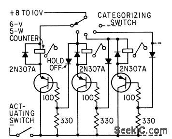
Diodes absorb flyback and prevent duplicate counts when categorized information ;is fed to banks of electromechanical counters.-R. L. lves , Reducing Errors in Category Counters, Electronics, 35:23, p 54-57. (View)
View full Circuit Diagram | Comments | Reading(832)
SPACECRAFT_COMPUTER_POWER_SWITCHING
Published:2009/7/12 21:49:00 Author:May

Conserves battlery power by automatically disconnecting sections of computer when they are nol in use. Q1 and Q2 serve as switch,while Q3 generates automatic reset pulse when power turns on.When control line is at ground,no power is supplied on output line.Q4 delays Power turnoff for short time after control signal drops.-R.A.Clift,Power Switching Trims Digital System Weight, Cost Electronics,39:12,p135-138. (View)
View full Circuit Diagram | Comments | Reading(758)
COMPUTER_VOICE
Published:2009/7/12 21:45:00 Author:May

This circuit will enable one to simulate the computer voice effect commonly heard in films, ads, and TV programs. It consists of two sections: an oscillator to provide the modulation signals, and the modulator itself. The oscillator uses a 555 timer chip in the astable multivibrator mode, and the frequency of operation has been set at about 10 Hz by the values given to R1, R2, and C1. A very simple modulator is used, but this is quite acceptable. Distortion produces new frequencies that help to change the voice signal and make it sound less like the original. A large amount of distortion is obviously not desirable because it would severely impair the intelligibility of the output signal. Transistor TR1 is used as a sort of voltage-controlled resistor, and, in conjunction with R4, it forms a voltage-controUed attenuator. (View)
View full Circuit Diagram | Comments | Reading(1600)
ARITHMETIC_CELL
Published:2009/7/12 20:28:00 Author:May

Uses 27 resistively-coupled tunnel diodes, powered from three-phase pulse supply. Repetition rate is 1 Mc.-T, Maguire, Computers Head for 1,000-Mc Opercttion, Electronics, 33:5, p55-59. (View)
View full Circuit Diagram | Comments | Reading(710)
TEMPERATURE_COEFFICI_ENT_COMPUTER
Published:2009/7/11 5:16:00 Author:May
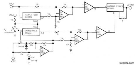
Circuit automatically measures and calculates temperature coefficients of analog circuits or devices. Silicon diode CR1 is used as temperature probe having forward drop of about 2 mV/ ℃. R adjusts output scale factor, FET-input opamp A1 converts forward voltage drop of temperature probe into high-level analog voltage that varies 325 mV/℃ from -10V at +55℃ to 10 V at -5℃. Output of A1 is applied to sample-and-hold circuit, while analog voltage from device under test is applied to second sample-and-hold. Momentary closing of S1 causes volt-age and temperature data to be stored in sample-and-hold circuits at start of test to bias a2 and A3. Outputs of these opamps can be positive or negative, butare made poshive by unity-gain absolute-value opamps A4 and A5. From these outputs, analog divider calculates temperature coefficient.-R. C. Gerdes, Temperature-Coefficient Measuring Circuit, EDN/EEE Magazine, Feb. 1, 1972, p 54. (View)
View full Circuit Diagram | Comments | Reading(745)
RESET_PROTECTION_FOR_COMPUTERS
Published:2009/7/9 22:46:00 Author:May
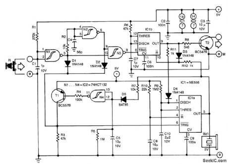
This protection circuit is inserted between the reset switch and the motherboard. The earth connection of the computer must be linked to terminal M of the protection circuit. The protection circuit can draw its power from the computer supply.
When the circuit has been fitted, operation of the reset switch will not immediately restart the computer. Instead, a buzzer will sound to alert you to the reset operation. The buzzer is actuated for 4 s by monostable IC1A, which is triggered by the reset switch. During these 4 s, the output, pin 5, of IC1A ensures that the reset function, pin 10, of IC1B is disabled. When the reset switch is operated again, monostable ICIB will be triggered and this starts the reset procedure. Transistor T2 is then switched on for 0.5 s and the buzzer is deactuated via R11 and D4.
The circuit around T1 and N4 ensures that IC1A can accept trigger pulses again 10 s after the mono time of IC1B has lapsed. This arrangement prevents, for example, children operating the reset switch. (View)
View full Circuit Diagram | Comments | Reading(1927)
8_bit_storage_register
Published:2009/7/21 21:24:00 Author:Jessie

8-bit storage register (courtesy Motorola Semiconductor Products Inc.). (View)
View full Circuit Diagram | Comments | Reading(2279)
Tape_recorder_position_indicator_controller_using_an_ICM7217A_28_pin_DIP
Published:2009/7/21 21:23:00 Author:Jessie

Tape recorder position indicator/controller using an ICM7217A 28-pin DIP. This circuit employs the up/down feature of the ICM7217 to keep track of the tape position. The not-equal and not-zero outputs can be used to control the recorder. To make the recorder stop at a particular point on the tape, the register can be set with the stop point and the equal output used to stop the recorder, either on fast forward, play or rewind. To have the recorder stop before the tape comes free of the reel on rewind a leader should be used. Resetting the counter at the starting point of the tape a few feet from the end of the leader allows the zero output to be used to stop the recorder on rewind. The 1 M resistor and 0.0047μF capacitor on the count input provides a time constant of about 5 ms to debounce the reel switch (courtesy Intersil, Inc.). (View)
View full Circuit Diagram | Comments | Reading(1927)
Dual_4_bit_storage_register
Published:2009/7/21 8:52:00 Author:Jessie
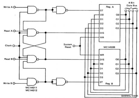
Dual 4-bit storage register (courtesy Motorola Semiconductor Products Inc.). (View)
View full Circuit Diagram | Comments | Reading(1927)
3_1_2_digit_parallel_data_acquisition_system_using_the_8052_7101_A_D_pair
Published:2009/7/21 8:50:00 Author:Jessie
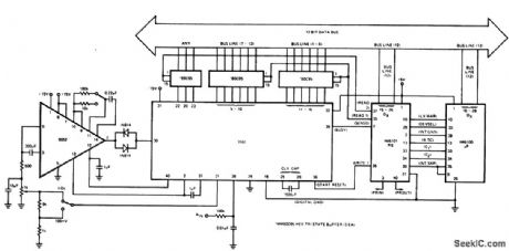
31/2-digit parallel data acquisition system using the 8052/7101 A/D pair (courtesy Intersil, Inc.). (View)
View full Circuit Diagram | Comments | Reading(708)
CMOS__keyboard_data_entry_system
Published:2009/7/21 8:43:00 Author:Jessie
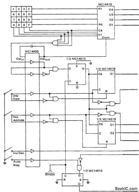

CMOS keyboard data entry system (courtesy Motorola Semiconductor Products Inc.). (View)
View full Circuit Diagram | Comments | Reading(2024)
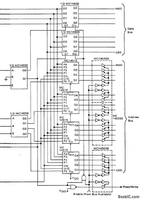
8_bit_binary_to_3_digit_decimal_display_decoder_for_8_bit_microprocessor_systems_with_256_by_4_PROM_three_7_segment_decoder_drivers_with_9374_input_latches_and_two_gates
Published:2009/7/21 8:39:00 Author:Jessie

8-bit binary to 3-digit decimal display decoder for 8-bit microprocessor systems with 256 by 4 PROM, three 7-segment decoder/drivers with 9374 input latches and two gates (courtesy Fairchild Semiconductor). (View)
View full Circuit Diagram | Comments | Reading(8883)
Synchronizing_two_M6802_microprocessors_on_one_bus
Published:2009/7/21 8:37:00 Author:Jessie
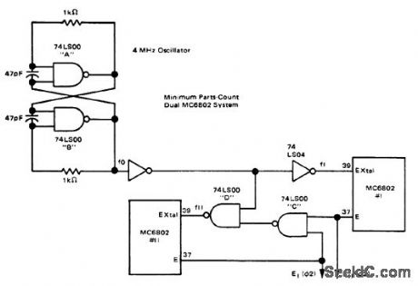
Synchronizig two M6802 microprocessors on one bus (courtesy Motorola Semiconductor Products Inc.). (View)
View full Circuit Diagram | Comments | Reading(904)
| Pages:20/39 1234567891011121314151617181920Under 20 |
Circuit Categories
power supply circuit
Amplifier Circuit
Basic Circuit
LED and Light Circuit
Sensor Circuit
Signal Processing
Electrical Equipment Circuit
Control Circuit
Remote Control Circuit
A/D-D/A Converter Circuit
Audio Circuit
Measuring and Test Circuit
Communication Circuit
Computer-Related Circuit
555 Circuit
Automotive Circuit
Repairing Circuit