Communication Circuit
VACUUM_TUBE_TRANSMITTER
Published:2009/7/14 21:11:00 Author:May | From:SeekIC

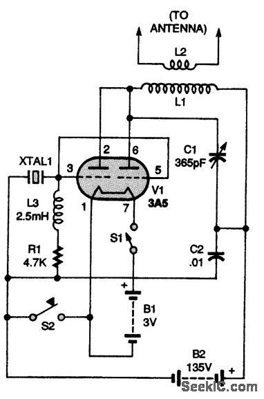
The schematic for the transmitter is shown in the figure. In the circuit, power is supplied by a 3V battery B1 and a 135-V battery B2. The latter battery, B2, can be replaced by a power-supply circuit. Switch S1 is used to turn the circuit on and off. The heart of the circuit is a 3A5 tube, V1. Both sections of V1 are connected in parallel in a conventional Miller oscillator. Resistor R1 sets the bias for the tube; the value of R1 might seem low to some because it is only 4700Ω, but keep in mind that V1 is a transmitting triode operating at class C. A 2.5-mH RF choke coil (L3) is needed to keep the radio frequency where it belongs. Capacitor C1 and inductor L1 resonate at the frequency of a 40-m (7- to 7.3-MHz) amateur crystal, XTAL1. Inductor L2 couples RF energy to an attached antenna; C2 is a bypass capacitor. Switch S2 is a telegraph-type key switch. That is used to generate the content of any transmissions you make. Transformer T1 provides isolation from the power line. The isolated ac voltage is rectified by diode D1 and filtered by capacitor C1.
Reprinted Url Of This Article:
http://www.seekic.com/circuit_diagram/Communication_Circuit/VACUUM_TUBE_TRANSMITTER.html
Print this Page | Comments | Reading(3)

Article Categories
power supply circuit
Amplifier Circuit
Basic Circuit
LED and Light Circuit
Sensor Circuit
Signal Processing
Electrical Equipment Circuit
Control Circuit
Remote Control Circuit
A/D-D/A Converter Circuit
Audio Circuit
Measuring and Test Circuit
Communication Circuit
Computer-Related Circuit
555 Circuit
Automotive Circuit
Repairing Circuit
Code: