Communication Circuit
TRACER_RECEIVER
Published:2009/7/8 4:04:00 Author:May | From:SeekIC

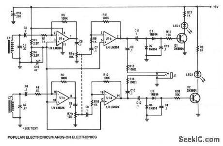
The tracer receiver is a stereo audio amplifier/detector circuit operating near 1 kHz. Inductors L1 and L2-hand-wound coils, consisting of 200 turns of #26 wire on 2-inch ferrite cores- are tuned to the operating frequency of the amplifier/detector. The received signal strength of each individual receiver is indicated by an LED. The audio output of the receiver is fed to a stereo headphone. That dual-receiver scheme helps in locating and tracking the hidden wire or cable by giving a directional output that indicates the cable's path.
The 1-kHz signal is picked up by L1 and coupled to the input of op amp U1a, which provides a gain of about 100 dB. The output of op amp U1a is fed through volume-control potentiometer R7 to the input of U1b, which magnifies the already amplified signal 100 times more. That puts the maximum gain of the receiver at about 10,000 dB. The output of U1b follows two paths: in the first path, the signal is couple through C9 and R13 to J1, and is used to drive one half of a stereo headphone.
In the other path, the signal is fed through a voltage doubling/detector circuit-consisting of Dl, D2, C11, and C13-that converts the amplified 1-kHz signal to the dc voltage that's used to drive Q1. When Q1 is turned on, LED1 lights, indicating a received signal.
Reprinted Url Of This Article:
http://www.seekic.com/circuit_diagram/Communication_Circuit/TRACER_RECEIVER.html
Print this Page | Comments | Reading(3)

Article Categories
power supply circuit
Amplifier Circuit
Basic Circuit
LED and Light Circuit
Sensor Circuit
Signal Processing
Electrical Equipment Circuit
Control Circuit
Remote Control Circuit
A/D-D/A Converter Circuit
Audio Circuit
Measuring and Test Circuit
Communication Circuit
Computer-Related Circuit
555 Circuit
Automotive Circuit
Repairing Circuit
Code: