Communication Circuit
REMOTE_SENSOR_LOOP_TRANSMITTER
Published:2009/7/6 8:49:00 Author:May | From:SeekIC

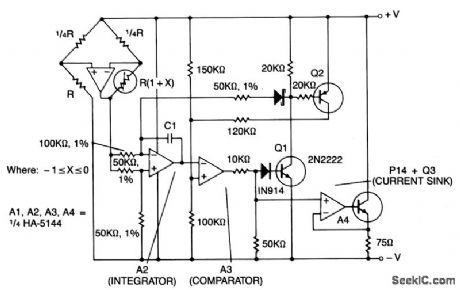
This circuit shows amplifier A1 as a sensor amplifier in a bridge configuration. Amplifiers A2 and A3 are configured as a voltage to frequency converter and A4 is used as the transmitter. This entire sensor/ transmitter can be powered directly from a 4 to 20 mA current loop.
The bridge configuration produces a linear output with respect to the changes in resistance of the sensor. The voltage at the output of Al causes the integrator output A2 to ramp down until it crosses the comparator threshold voltage of A3. A3 turns on Q1 and Q2. A1 causes the output of A2 to ramp up at a rate nearly equal to its negative slope, while Q2 provides hysteresis for the comparator. In addition, Q1 and Q2 help eliminate changes in power supply loop voltage. Amplifier A4 and Q3 are configured as a constant current sink which turns on when the comparator current increases. The resulting increase in loop current transmits the frequency of the V/F converter back to the control circuitry.
Reprinted Url Of This Article:
http://www.seekic.com/circuit_diagram/Communication_Circuit/REMOTE_SENSOR_LOOP_TRANSMITTER.html
Print this Page | Comments | Reading(3)

Article Categories
power supply circuit
Amplifier Circuit
Basic Circuit
LED and Light Circuit
Sensor Circuit
Signal Processing
Electrical Equipment Circuit
Control Circuit
Remote Control Circuit
A/D-D/A Converter Circuit
Audio Circuit
Measuring and Test Circuit
Communication Circuit
Computer-Related Circuit
555 Circuit
Automotive Circuit
Repairing Circuit
Code: