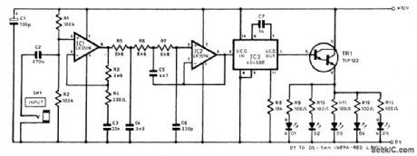
Communication Circuit
MONO_CORDLESS_HEADPHONE_IR_TRANSMITTER
Published:2009/7/14 7:30:00 Author:May | From:SeekIC

The preemphasis is applied by IC1, which is basically just an op amp used in the noninverting mode. At low and middle frequencies, the impedance of capacitor C3 is high in relation to the resistance of R3. Consequently, there is virtually 100 percent negative feedback through resistor R3, and IC1 has a closed-loop gain of little more than unity. At higher frequencies, the impedance of C3 is relatively low, and a significant proportion of the feedback through R3 is decoupled. This gives a closed-loop voltage gain that steadily rises with increased input frequency, with almost 20 dB of gain being provided at the highest audio frequencies. Resistor R4 limits the closed-loop voltage gain of IC1 at frequencies above the audio range. The low-pass filter is a conventional third-order (18 dB/octave) type based on IC2. This filter gives fractionally less than the full 20-kHz audio bandwidth, but does not significantly impair the quality of the input signal. A CMOS “micropower” PLL is used for IC3, but, in this circuit, only the VCO stage is utilized. No connections are made to any of the other sections of IC3. The output of IC2 is direct-coupled to the control input of the VCO (IC3 pin 9). Capacitor C7 and resistor R8 are the VCO timing components, and they set the center frequency at roughly 100 kHz. Transistor TR1 is a high-gain power Darlington device, which is used here as an emitter-follower buffer stage. This can easily source the 500-mA ON current of the LEDs. A bank of five LEDs is used, and each one has a separate current-limiting resistor (R9 to R13).
Reprinted Url Of This Article:
http://www.seekic.com/circuit_diagram/Communication_Circuit/MONO_CORDLESS_HEADPHONE_IR_TRANSMITTER.html
Print this Page | Comments | Reading(3)

Article Categories
power supply circuit
Amplifier Circuit
Basic Circuit
LED and Light Circuit
Sensor Circuit
Signal Processing
Electrical Equipment Circuit
Control Circuit
Remote Control Circuit
A/D-D/A Converter Circuit
Audio Circuit
Measuring and Test Circuit
Communication Circuit
Computer-Related Circuit
555 Circuit
Automotive Circuit
Repairing Circuit
Code: