Communication Circuit
MONO_CORDLESS_HEADPHONE_IR_RECEIVER
Published:2009/7/14 7:37:00 Author:May | From:SeekIC

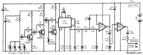
The full receiver circuit diagram appears in the figure. As many as four infrared detector can be used (D1 to D4 ). They are wired in parallel and used in the reverse-biased mode, and dark conditions only very small leakage currents flow. The pulses of infrared from the transmitter result in increased leakage currents, which generate small negative pulses at the cathodes (k) of the diodes. Transistor TR1 is used as a low-noise preamplifier and buffer stage. The majority of the voltage gain is provided by transistors TR2 and TR3, which are also common-emitter stages. These provide a combined voltage gain of over 80dB. The signal from TR3 is connected to one of the phase comparator inputs of IC1 (pin 14 ). This IC provides demodulation and is a CMOS 4046BE p.l.d. Resistor R10 and capacitor C6 are the timing components for the VCO,and they set the center frequency at approximately 100 kHz. Resistor R10 and capacitor C7 form a simple low-pass filter between the phase comparator’s output at pin 2 and the input of the VCO at pin 9. The audio output signal is obtained from the low-pass filter via an integral source-follower stage. The output from IC2 is fed to resistor R16 and capacitor C12, which form a simple low-pass filter that provides the deemphasis. The signal is then fed to the input of IC3, which is a small class-B audio power amplifier. The current consumption of the receiver is about 12 mA.
Reprinted Url Of This Article:
http://www.seekic.com/circuit_diagram/Communication_Circuit/MONO_CORDLESS_HEADPHONE_IR_RECEIVER.html
Print this Page | Comments | Reading(3)

Article Categories
power supply circuit
Amplifier Circuit
Basic Circuit
LED and Light Circuit
Sensor Circuit
Signal Processing
Electrical Equipment Circuit
Control Circuit
Remote Control Circuit
A/D-D/A Converter Circuit
Audio Circuit
Measuring and Test Circuit
Communication Circuit
Computer-Related Circuit
555 Circuit
Automotive Circuit
Repairing Circuit
Code: