Communication Circuit
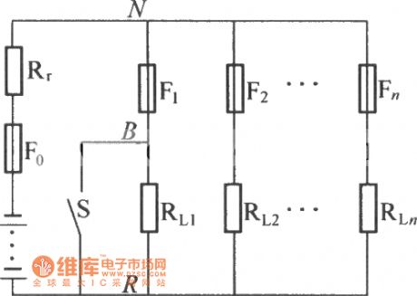
Low resistance distribution circuit diagram
Published:2014/2/17 23:11:00 Author: | Keyword: Low resistance distribution circuit diagram, | From:SeekIC

As shown in figure is low resistance distribution diagram, which is suitable for battery internal resistance R, RLn RL1 ~ for load distribution; From F1 to Fn distribution fuse, fuse F0 for battery, 2 thick line shows the total bus-bar up and down. Switch short-circuit the assumption S RL1 short-circuit, when F1 before has not fuse, at this time due to the battery internal resistance is greater than the resistance of the F1, between N and R will fall to the low voltage, at the same time, because the loop current is basically determined by the battery voltage and internal resistance of the battery, so the short circuit current is great. When F1 fuse, fuse because F1 before the short circuit current is big, the current rate di/dt is big also, in the N, R, two points on the equivalent inductance of the induction electric potential L x di/dt will form a big rush. At this point, the voltage between N and R first fell to zero in an instant, and then generate a high peak voltage. The docking will be on the same bus impact other load distribution in the whole system. Low resistance distribution, the load distribution is not completely independent, between many points against road effectively improve the reliability of communication system.
Reprinted Url Of This Article:
http://www.seekic.com/circuit_diagram/Communication_Circuit/Low_resistance_distribution_circuit_diagram.html
Print this Page | Comments | Reading(3)

Article Categories
power supply circuit
Amplifier Circuit
Basic Circuit
LED and Light Circuit
Sensor Circuit
Signal Processing
Electrical Equipment Circuit
Control Circuit
Remote Control Circuit
A/D-D/A Converter Circuit
Audio Circuit
Measuring and Test Circuit
Communication Circuit
Computer-Related Circuit
555 Circuit
Automotive Circuit
Repairing Circuit
Code: