Communication Circuit
IR_REMOTE_CONTROL_RECEIVER
Published:2009/7/14 8:16:00 Author:May | From:SeekIC

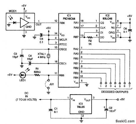
A schematic diagram of the remote-control receiver is shown. The heart of the circuit is IC1, a PIC16C54 8-bit CMOS manufactured by Microchip. The microcontroller stores its data in IC2, a 93LC46 1-kbit serial EEPROM (electrically erasable programmable read-only ntemory), also manufactured by Microchip. In this application, the 93LC46 has a three-line interface with the microcontroller. The three lines are CHIP SELECT, CLOCK, and DATA IN/OUT. Because DATA IN and DATA OUT share the same line, a resistor (R2)limits the current flow during transitions between writing and reading when there are conflicting logic levels. The microcontroller communicates with the 93LC46 by placing a logic high on the CHIP SELECT pin. Data are then transferred serially to and from the 93LC46 on the positive transition of the CLOCK line. Each read or write function is preceded by a start bit, an opcode identifying the function to be performed (read, write, etc.), then a 7-bit address; this is followed by the 8 bits of data which are being written to or read from that address. Immediately preceding and following all write operations, the microcontroller sends instructions to the 93LC46, which enables or disables the write function, thereby protecting the data that have been stored. In the programming mode, IC1 reads an IR data stream from MOD1 and converts it to data patterns that can be stored in IC2. These data patterns are held for comparison while the unit is in normal operation. Power for the circuit is conditioned by IC3, a 78L05 low-current, 5-V regulator, which will accept any dc input voltage between 7 and 25 V. Capacitors C1 and C2 stabilize the operation of the regulator. Crystal XTAL1 sets the internal oscillator of IC1 to 4 MHz. Jumper JU1 consists of two closely spaced pads on the PC board that, when momentarily jumpered with a screwdriver or other piece of metal, places IC1 in the programming mode and lights LED1. The source and object code are available on the Gernsback BBS (516-293-2283, v.32, v.42bis) as a file called IREC.ZIP for those who wish to program their own PICs and have the proper equipment to do so.
Reprinted Url Of This Article:
http://www.seekic.com/circuit_diagram/Communication_Circuit/IR_REMOTE_CONTROL_RECEIVER.html
Print this Page | Comments | Reading(3)

Article Categories
power supply circuit
Amplifier Circuit
Basic Circuit
LED and Light Circuit
Sensor Circuit
Signal Processing
Electrical Equipment Circuit
Control Circuit
Remote Control Circuit
A/D-D/A Converter Circuit
Audio Circuit
Measuring and Test Circuit
Communication Circuit
Computer-Related Circuit
555 Circuit
Automotive Circuit
Repairing Circuit
Code: