Communication Circuit
INTERMEDIATE_FREQUENCY_TRANSMITTER
Published:2009/7/14 20:50:00 Author:May | From:SeekIC

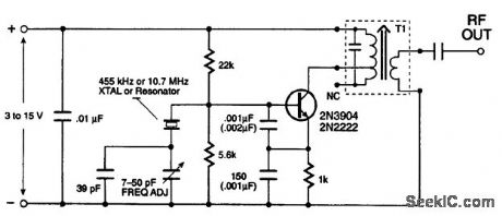
The oscillator transmitter circuit is a variation of the Colpitts configuration. This particular circuit exhibits excellent frequency stability, good isolation between the frequency reference and the output, and isolated low output impedance. If you have the correct crystal on hand, that's fine. If not, a ceramic resonator will also work with the components shown. The tuned circuit T1 is an IF can, salvaged from an old AM and FM receiver; be sure that it has a primary tap. The primary of the 455-KHz, IF can will measure 3 to 5Ω, and the 10.7-MHz IF can will measure less than 1Ω; these measurements will help you to identify the correct inductor. The components in parentheses should be used for the 455-kHz transmitter.
Reprinted Url Of This Article:
http://www.seekic.com/circuit_diagram/Communication_Circuit/INTERMEDIATE_FREQUENCY_TRANSMITTER.html
Print this Page | Comments | Reading(3)

Article Categories
power supply circuit
Amplifier Circuit
Basic Circuit
LED and Light Circuit
Sensor Circuit
Signal Processing
Electrical Equipment Circuit
Control Circuit
Remote Control Circuit
A/D-D/A Converter Circuit
Audio Circuit
Measuring and Test Circuit
Communication Circuit
Computer-Related Circuit
555 Circuit
Automotive Circuit
Repairing Circuit
Code: