Communication Circuit
INFRARED_RECEIVER
Published:2009/7/1 0:56:00 Author:May | From:SeekIC

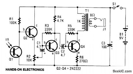
The circuit consists of Q1-a phototransistor that responds to an intensity of amplitude-modulated IR light source-and a three-stage, high-gain audio amplifier.Transformer T1 is used to match the output impedance of the receiver to today's popular low-impedance (low-Z) headphones; but if a set of 1000-2000 ohm, magnetic (not crystal), high-impedance (high-Z) phones are to be used, remove T1 and connect the high-Z phones in place of T1's primary winding-the 1000-ohm winding.
Reprinted Url Of This Article:
http://www.seekic.com/circuit_diagram/Communication_Circuit/INFRARED_RECEIVER.html
Print this Page | Comments | Reading(3)

Article Categories
power supply circuit
Amplifier Circuit
Basic Circuit
LED and Light Circuit
Sensor Circuit
Signal Processing
Electrical Equipment Circuit
Control Circuit
Remote Control Circuit
A/D-D/A Converter Circuit
Audio Circuit
Measuring and Test Circuit
Communication Circuit
Computer-Related Circuit
555 Circuit
Automotive Circuit
Repairing Circuit
Code: