Communication Circuit
INFRARED_ALARM_RECEIVER
Published:2009/7/14 7:33:00 Author:May | From:SeekIC

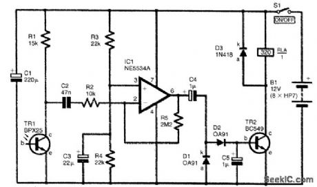
The full circuit diagram for the infrared receiver is given here. TR1 is a phototransistor, and it is used in a common-emitter amplifier. However, no bias current is fed to the base (b) terrrtinal of TR1.The collector (c) current is governed by the light level received by TR1. The higher the received light level, the higher the current flow. The pulses of infrared from the transmitter therefore produce pulses of leakage current through TR1, which give small negative pulses at TR1's collector. The output signal for TR1's collector is coupled by capacitor C2 to a high-gain inverting amplifier based on IC1. Resistors R2 and R5 ire the negative-feedback network, and these set the closed-loop voltage gain of IC1 at 220 times. Capacitor C4 couples the amplified output signal from IC1 pin 6 to a conventional half-wave rectifier and smoothing circuit (D1, D2, and C5). Germanium, rather than silicon, diodes are used in the rectifier, because germanium types have a lower forward voltage drop.This gives slightly improved sensitivity. The positive dc signal developed across capacitor C5 drives the base of TR2, which is a simple common-emitter switch that controls the relay RLA coil.
Reprinted Url Of This Article:
http://www.seekic.com/circuit_diagram/Communication_Circuit/INFRARED_ALARM_RECEIVER.html
Print this Page | Comments | Reading(3)

Article Categories
power supply circuit
Amplifier Circuit
Basic Circuit
LED and Light Circuit
Sensor Circuit
Signal Processing
Electrical Equipment Circuit
Control Circuit
Remote Control Circuit
A/D-D/A Converter Circuit
Audio Circuit
Measuring and Test Circuit
Communication Circuit
Computer-Related Circuit
555 Circuit
Automotive Circuit
Repairing Circuit
Code: