Communication Circuit
FIBER_OPTIC_TRANSMITTER
Published:2009/7/6 4:30:00 Author:May | From:SeekIC

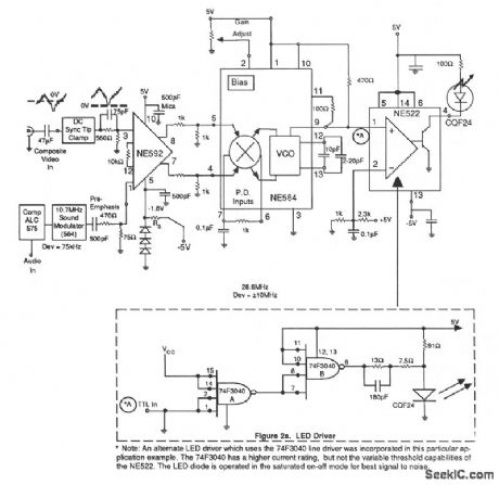
This receiver circuit consists of wideband differential amplifier NE592, VCO NE564 and LED driver NE522-the high-speed comparator. The video signal is ac coupled into the modulator preamplifier and followed by a sync tip clamp to provide dc restoration on the composite video signal and to prevent variation of modulation deviation with varying picture content. A video signal level of 250 to 300 mV peak is required to maintain optimum picture modulation. Frequency compensation (preemphasis) is inserted in the form of a passive rc lead network at the input to the NE592 differential amplifier. The main FM modulator consists of an NE564 used only as a linear wideband VCO, but the other sections of the device are not used. Differential dc coupling to the VCO terminals is attained via the loop filter terminals, pins 4 and 5.
Reprinted Url Of This Article:
http://www.seekic.com/circuit_diagram/Communication_Circuit/FIBER_OPTIC_TRANSMITTER.html
Print this Page | Comments | Reading(3)

Article Categories
power supply circuit
Amplifier Circuit
Basic Circuit
LED and Light Circuit
Sensor Circuit
Signal Processing
Electrical Equipment Circuit
Control Circuit
Remote Control Circuit
A/D-D/A Converter Circuit
Audio Circuit
Measuring and Test Circuit
Communication Circuit
Computer-Related Circuit
555 Circuit
Automotive Circuit
Repairing Circuit
Code: