Communication Circuit
DIGITAL_IR_TRANSMITTER
Published:2009/7/7 8:27:00 Author:May | From:SeekIC

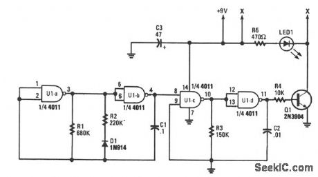
Gates U1a and U1b are configured as a low-frequency oscillator. The output waveform at pin 11 is nonsymmetrical with the positive portion of the signal, making up only 20% of the time period.Diode D1, a 1N914 general-purpose unit, together with C1, R1, and R2, determine the on time for the positive portion of the output waveform. The off, or negative portion of the output waveform, depends mainly on the values of R1 and C1. The operating frequency of that oscillator is about 11 Hz. The second oscillator consists of U1c and U1d, which outputs on almost symmetrical waveform at a frequency of about 400 Hz. The output of first oscillator U1a/U1b is fed to pin 8 of U1c to key second oscillator U1c/U1d on and off at about 11 Hz, with the on time limited to about 20% of the time period (about 15 ms).The output waveform of the second oscillator is fed to the base of Q1, which is used to drive IR diode LED1 in short bursts. Pulsing LED1 helps to save battery power, and also allows each circuit to be given its own special sound footprint.By changing any of the values of R1, R2, R3, C1, or C2, the sound footprint can be varied. As the component values are increased, the oscillator's frequency goes down, and as the values are decreased, the frequency goes up.
Reprinted Url Of This Article:
http://www.seekic.com/circuit_diagram/Communication_Circuit/DIGITAL_IR_TRANSMITTER.html
Print this Page | Comments | Reading(3)

Article Categories
power supply circuit
Amplifier Circuit
Basic Circuit
LED and Light Circuit
Sensor Circuit
Signal Processing
Electrical Equipment Circuit
Control Circuit
Remote Control Circuit
A/D-D/A Converter Circuit
Audio Circuit
Measuring and Test Circuit
Communication Circuit
Computer-Related Circuit
555 Circuit
Automotive Circuit
Repairing Circuit
Code: