Communication Circuit
BA1404_STEREO_TRANSMITTER
Published:2009/7/14 20:54:00 Author:May | From:SeekIC

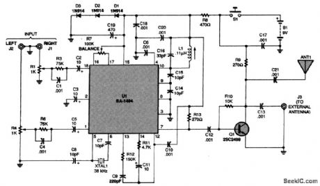
At the heart of the schematic for the FM stereo transmitter is the BA1404 FM stereo transmitter IC. Note that there is no R2 or R5 circuit.
The circuit uses the BA1404 IC (Rohm semiconductor) to implement a complete low-power FM stereo transmitter in the 88- to 92-MHz band. Line-level audio is fed to U1, the BA1404. Xtal1 is a 38-kHz crystal, and the RE oscillator tank C16/L1 (and associated components) determine RE frequency. The circuit should be carefully constructed to minimize frequency drift and microphonics. Q1 is a buffer amplifier to reduce oscillator frequency pulling. A 9-V supply is used to power the circuit.
Reprinted Url Of This Article:
http://www.seekic.com/circuit_diagram/Communication_Circuit/BA1404_STEREO_TRANSMITTER.html
Print this Page | Comments | Reading(3)

Article Categories
power supply circuit
Amplifier Circuit
Basic Circuit
LED and Light Circuit
Sensor Circuit
Signal Processing
Electrical Equipment Circuit
Control Circuit
Remote Control Circuit
A/D-D/A Converter Circuit
Audio Circuit
Measuring and Test Circuit
Communication Circuit
Computer-Related Circuit
555 Circuit
Automotive Circuit
Repairing Circuit
Code: