Communication Circuit
AM_TONE_TRANSMITTER
Published:2009/7/14 20:58:00 Author:May | From:SeekIC

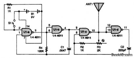
Power for the circuit is supplied by B1, a 9-V battery. Two sections of a 4011 NAND gate, U1-c and U1-d, are used as part of a radio-frequency (RE) oscillator (carrier). The other two sections, U1-a and U1-b, are used in an audio-frequency (AP) oscillator (modulator). Switch S1 enables and disables the modulation to allow the transfer of an intelligent message with the transmitter. When you press S1, the AP oscillator composed of U1-a, U1-b, R4, and C1 starts generating an audio signal.That signal gates the RE oscillator composed of U1-c, U1-d, R2, R3, and C2 on and off. When on, the RE oscillator runs at 1 MHz. The resulting output is sent out ANT1 as an AM signal.
Reprinted Url Of This Article:
http://www.seekic.com/circuit_diagram/Communication_Circuit/AM_TONE_TRANSMITTER.html
Print this Page | Comments | Reading(3)

Article Categories
power supply circuit
Amplifier Circuit
Basic Circuit
LED and Light Circuit
Sensor Circuit
Signal Processing
Electrical Equipment Circuit
Control Circuit
Remote Control Circuit
A/D-D/A Converter Circuit
Audio Circuit
Measuring and Test Circuit
Communication Circuit
Computer-Related Circuit
555 Circuit
Automotive Circuit
Repairing Circuit
Code: