Communication Circuit
4_CHANNELVHF_FM_SCANNER
Published:2009/7/13 21:40:00 Author:May | From:SeekIC

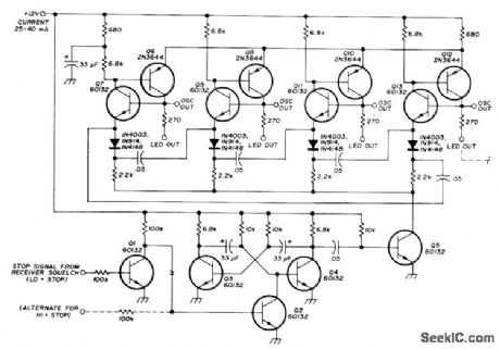
Discrete components permit simpler readout, with any number of channels and any desired scan rate. Operates directly from 10-15 V power supply without regulation, and has low current drain. Can be used with either positive or negative logic from squelch circuit, so scanning can be stopped with either positive or ground signal. Any voltage from a few volts up will stop scanning. Q3 and Q4 form astable MVBR operating at about 10 pulses per second. Q2 turns on to stop MVBR when base of Q2 is high. Inverter Q1 provides proper polarity of signal to operate Q2. Q6-Q13 form 4-stage ring counter. Pulsing by Q5 serves to pass high output from stage to stage in endless ring pattern. When squelch stops pulsing action, counter stops stepping and output of one counter stage stays high, providing 5-V output for enabling corresponding oscillator and driving LED for that channel, Article gives connections to oscillator for almost any FM transceiver or receiver, along with modifications for changing scan speed and number of channels.-J. Vogt, Improved Channel Scanner for VHF FMJ Ham Radio, Nov, 1974,p26-31.
Reprinted Url Of This Article:
http://www.seekic.com/circuit_diagram/Communication_Circuit/4_CHANNELVHF_FM_SCANNER.html
Print this Page | Comments | Reading(3)

Article Categories
power supply circuit
Amplifier Circuit
Basic Circuit
LED and Light Circuit
Sensor Circuit
Signal Processing
Electrical Equipment Circuit
Control Circuit
Remote Control Circuit
A/D-D/A Converter Circuit
Audio Circuit
Measuring and Test Circuit
Communication Circuit
Computer-Related Circuit
555 Circuit
Automotive Circuit
Repairing Circuit
Code: