Basic Circuit
_TIMER_CIRCUIT
Published:2009/7/7 4:08:00 Author:May | From:SeekIC

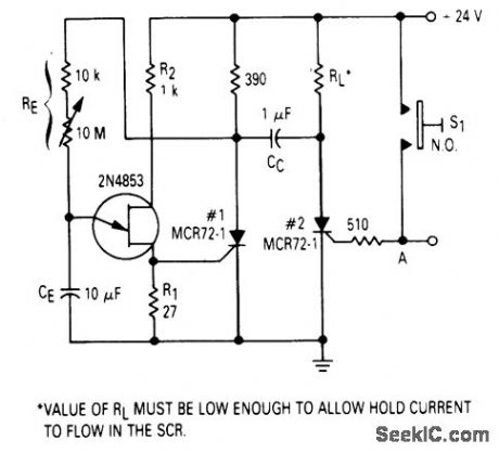
After one cycle of operation, SCR 1 will be on, and a low value of voltage is applied to the UJT emitter circuit, interrupting the timing function. When pushbutton S1 is pushed, or a positive going pulse is applied at point A, SCR 2 will turn on, and SCR 1 will be turned off by commutating capacitor CC. With SCR 1 off, the supply voltage will be applied to RE and the circuit will begin timing again. After a period of time determined by the setting of RE, the UJT witt fire and turn SCR 1 on and commutate SCR 2 off. The time delay is determined by the charge time of the capacitor
Reprinted Url Of This Article:
http://www.seekic.com/circuit_diagram/Basic_Circuit/_TIMER_CIRCUIT.html
Print this Page | Comments | Reading(3)

Article Categories
power supply circuit
Amplifier Circuit
Basic Circuit
LED and Light Circuit
Sensor Circuit
Signal Processing
Electrical Equipment Circuit
Control Circuit
Remote Control Circuit
A/D-D/A Converter Circuit
Audio Circuit
Measuring and Test Circuit
Communication Circuit
Computer-Related Circuit
555 Circuit
Automotive Circuit
Repairing Circuit
Code: