Basic Circuit
Water level indicator circuit (4)
Published:2011/5/29 22:55:00 Author:Christina | Keyword: Water level, indicator | From:SeekIC

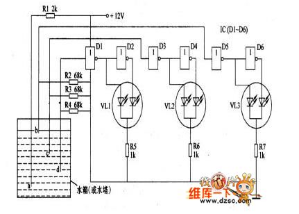
The operating principle: this circuit is composed of the water level detection circuit and the LED driving circuit, as the figure shows.
The water level detection circuit is composed of the water level detection electrodes a-d, the resistors Rl-R4, the Dl, D3, D5 of the NAND gate ICs Dl-D6.
The D driving circuit is composed of the IC, the discoloration LEDs LEDl-LED3 and the resistors R5-R7.
When the water level detection electrode d is in the water, the electrode connects with the electrode d through the resistance of water, the NAND gate Dl's input port has the high electrical level, and it's output port has the low electrical level, D2's output port has the high electrical level. When the water level is lower than the electrode d, Dl's input port has the low electrical level and the output port has the high electrical level, D2's output port has the low electrical level to make the VL1 to send out the red light.
Reprinted Url Of This Article:
http://www.seekic.com/circuit_diagram/Basic_Circuit/Water_level_indicator_circuit_4.html
Print this Page | Comments | Reading(3)

Article Categories
power supply circuit
Amplifier Circuit
Basic Circuit
LED and Light Circuit
Sensor Circuit
Signal Processing
Electrical Equipment Circuit
Control Circuit
Remote Control Circuit
A/D-D/A Converter Circuit
Audio Circuit
Measuring and Test Circuit
Communication Circuit
Computer-Related Circuit
555 Circuit
Automotive Circuit
Repairing Circuit
Code: