Basic Circuit
Water level indicator circuit (1)
Published:2011/5/26 22:04:00 Author:Christina | Keyword: Water level, indicator | From:SeekIC

Circuit operating principle
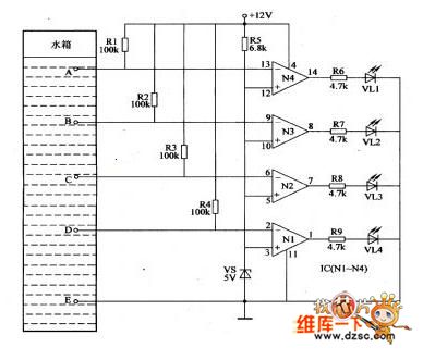
This water level indicator circuit is composed of the water level detection electrode A-E, the voltage stabilization diode VS, the resistors Rl-R9, the four op-amps Nl-N4 and the LED VLl-VM, as the figure shows.
When there is no water in the tank, the reversed-phase input port voltages of the op-amps Nl-N4 are higher than +5V, so the Nl-N4 output the low electrical level, the LEDs VLl-VL4 turn off.
When the water level of the tank gets to the electrode D, the water resistance connects the electrode D with the electrode E to make the operational amplifier Nl's inverting input port (pin-2) voltage lower than +5V.
Reprinted Url Of This Article:
http://www.seekic.com/circuit_diagram/Basic_Circuit/Water_level_indicator_circuit_1.html
Print this Page | Comments | Reading(3)

Article Categories
power supply circuit
Amplifier Circuit
Basic Circuit
LED and Light Circuit
Sensor Circuit
Signal Processing
Electrical Equipment Circuit
Control Circuit
Remote Control Circuit
A/D-D/A Converter Circuit
Audio Circuit
Measuring and Test Circuit
Communication Circuit
Computer-Related Circuit
555 Circuit
Automotive Circuit
Repairing Circuit
Code: