Basic Circuit
Watchdog_timer_to_prevent_lock_up
Published:2009/7/24 12:39:00 Author:Jessie | From:SeekIC

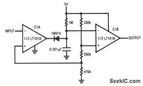
This circuit uses both sections of an LT1018 to prevent lock-up in processor-based systems. Such lock-up can occur if the system misses an instruction because of transients in hardware or software, and usually results in loss of pulses somewhere in the system. This circuit issues a reset command in response to such a pulse loss. Normally, a pulse train appears at the circuit input and causes the C1A output to pulse low. The diode path discharges the 0.01-μF capacitor each time the C1A output goes low. Interruption of the input pulse train (after the 7th vertical division) allows the capacitor to charge beyond the C1B threshold, and triggers C1B low. This pulse can be used to reset the system (applied to the microprocessor RST input). The C1B negative-input RC values can be adjusted to accommodate various input pulse-repetition rates. Linear Technology, Linear Applications Handbook, 1990, p. AN31-10.
Reprinted Url Of This Article:
http://www.seekic.com/circuit_diagram/Basic_Circuit/Watchdog_timer_to_prevent_lock_up.html
Print this Page | Comments | Reading(3)

Article Categories
power supply circuit
Amplifier Circuit
Basic Circuit
LED and Light Circuit
Sensor Circuit
Signal Processing
Electrical Equipment Circuit
Control Circuit
Remote Control Circuit
A/D-D/A Converter Circuit
Audio Circuit
Measuring and Test Circuit
Communication Circuit
Computer-Related Circuit
555 Circuit
Automotive Circuit
Repairing Circuit
Code: