Basic Circuit
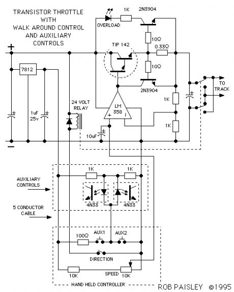
Walkaround Throttle With Auxiliary Controls Schematic
Published:2013/6/25 21:57:00 Author:muriel | Keyword: Walkaround Throttle, Auxiliary Controls Schematic | From:SeekIC

A variation on the walkaround throttle is in the next circuit. If extra wires are added to the control cable they can be put to use for operating accessories on the layout.
For every extra wire 2 such loads can be controlled. Electromagnetic uncoupling ramps could be turned on and off, train whistles could be blown or a reverse loop switch can be thrown after the train has passed.By using 4N33 Darlington output Optoisolators as low power relays and adding two push buttons or a toggle switch to the hand held controller a wide variety of external devices could be operated with only a small current draw on the throttle circuit itself.
Unplugable operation would still be a feasible option even with six wires in the control cable. This would allow four auxiliary control outputs.
The optoisolator by itself can only handle a load current of 20 milliamps, larger load currents require adding another transistor. The next drawing is shows a more detailed view of the auxiliary outputs.
Reprinted Url Of This Article:
http://www.seekic.com/circuit_diagram/Basic_Circuit/Walkaround_Throttle_With_Auxiliary_Controls_Schematic.html
Print this Page | Comments | Reading(3)

Article Categories
power supply circuit
Amplifier Circuit
Basic Circuit
LED and Light Circuit
Sensor Circuit
Signal Processing
Electrical Equipment Circuit
Control Circuit
Remote Control Circuit
A/D-D/A Converter Circuit
Audio Circuit
Measuring and Test Circuit
Communication Circuit
Computer-Related Circuit
555 Circuit
Automotive Circuit
Repairing Circuit
Code: