Basic Circuit
Voltage-controlled duty cycle oscillator circuit
Published:2011/8/7 4:14:00 Author:nelly | Keyword: Voltage-controlled, duty cycle, oscillator | From:SeekIC
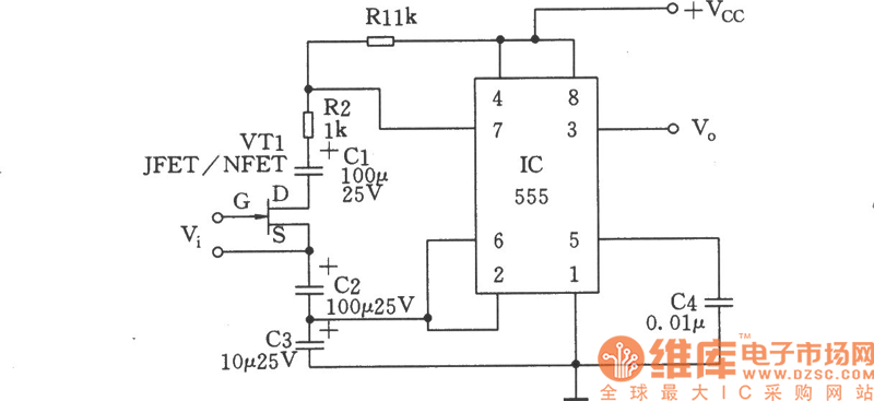
The picture shows the self-excited multivibrator which is composed of 555 timer. FET VTl is used as the voltage-controlled resistor (VVR). Changing the voltage gate source VGS can alter the resistor between JEFT drain (D) and source (S). Two coupling capacitors can avoid the DC voltage of circuit’s other part from influencing VTl. In order not to make the coupling capacitor influence the charging and discharging time of 555 timer. The values of coupling capacitor C1 and C2 are ten times of timing capacitor, meanwhile, a resistance RDS can be achieved between the D pole and S pole of VTl.
Reprinted Url Of This Article:
http://www.seekic.com/circuit_diagram/Basic_Circuit/Voltage_controlled_duty_cycle_oscillator_circuit.html
Print this Page | Comments | Reading(3)

Article Categories
power supply circuit
Amplifier Circuit
Basic Circuit
LED and Light Circuit
Sensor Circuit
Signal Processing
Electrical Equipment Circuit
Control Circuit
Remote Control Circuit
A/D-D/A Converter Circuit
Audio Circuit
Measuring and Test Circuit
Communication Circuit
Computer-Related Circuit
555 Circuit
Automotive Circuit
Repairing Circuit
Code: