Basic Circuit
Voltage / frequency and frequency / voltage conversion circuit composed of VFC320
Published:2011/7/6 19:28:00 Author:Lucas | Keyword: Voltage / frequency conversion, frequency / voltage conversion | From:SeekIC
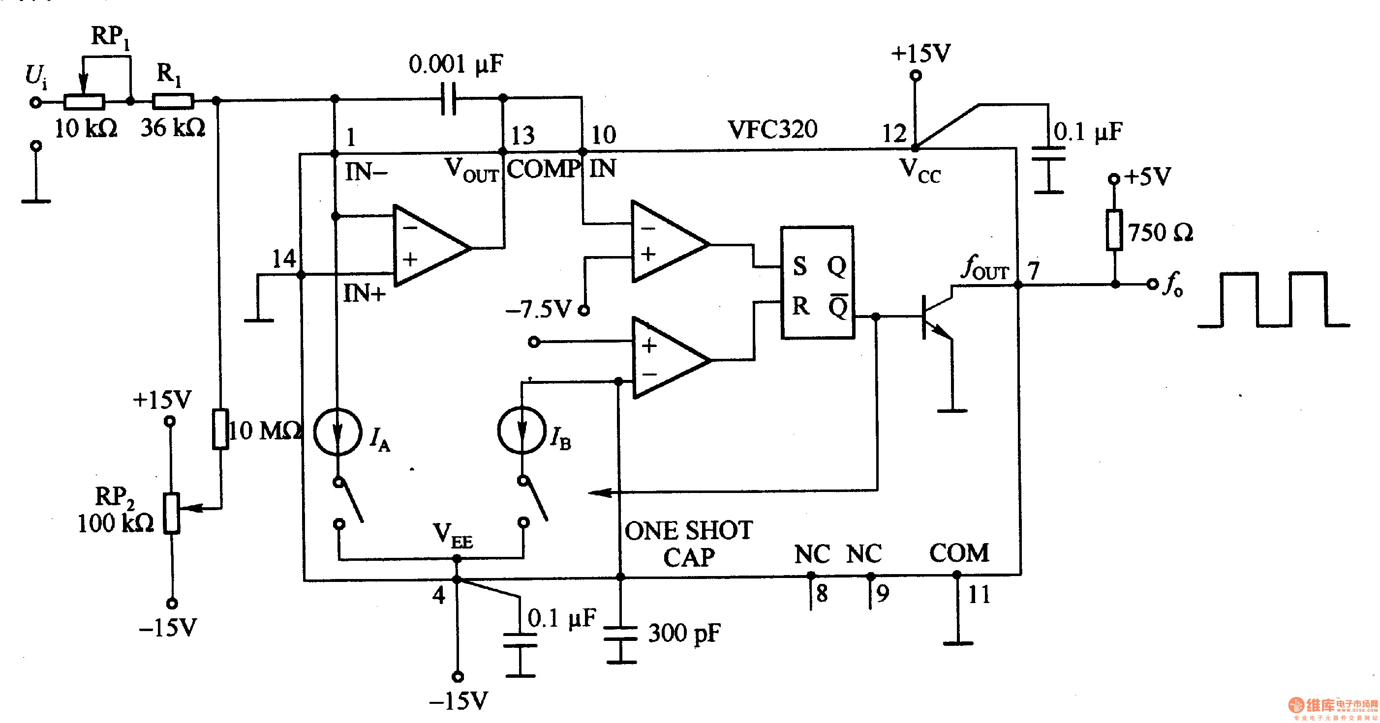
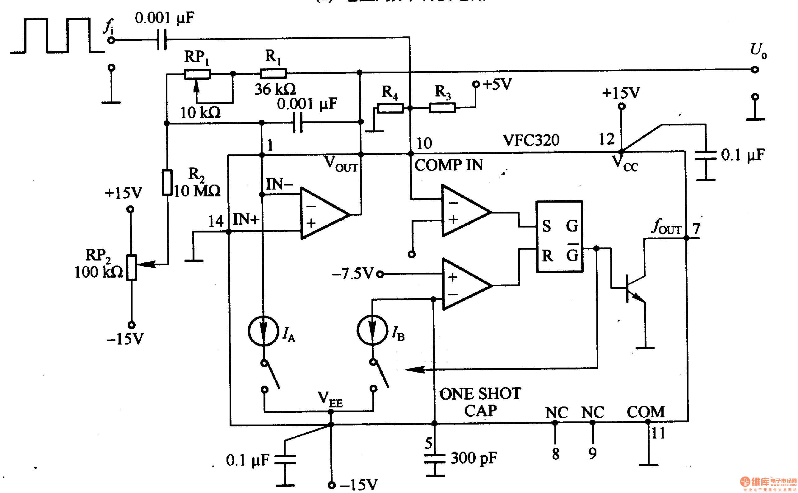
Figure 1-22 (a) shows the circuit which could convert 0-+lOV input voltage Ui into the pulse with 0 -1OOkHz output frequency, and pin 7 of VFC320 is connected a resistor to directly connect to standard logic. Figure 1-22 (b) shows the the circuit which could convert the pulse with 0-100KHz input frequency into 0-+lOV output voltage UO. If the signal counter of CPU is for voltage / frequency converter output, then it can be used as the A / D converter with strong anti-noise ability; If the frequency / voltage converter is used in combination with the optical chopper, the motor speed can form analog voltage conversion circuit.
Reprinted Url Of This Article:
http://www.seekic.com/circuit_diagram/Basic_Circuit/Voltage___frequency_and_frequency___voltage_conversion_circuit_composed_of_VFC320.html
Print this Page | Comments | Reading(3)

Article Categories
power supply circuit
Amplifier Circuit
Basic Circuit
LED and Light Circuit
Sensor Circuit
Signal Processing
Electrical Equipment Circuit
Control Circuit
Remote Control Circuit
A/D-D/A Converter Circuit
Audio Circuit
Measuring and Test Circuit
Communication Circuit
Computer-Related Circuit
555 Circuit
Automotive Circuit
Repairing Circuit
Code: