Basic Circuit
VSUBPP_SUB_handshake_circuit
Published:2009/7/23 22:11:00 Author:Jessie | From:SeekIC

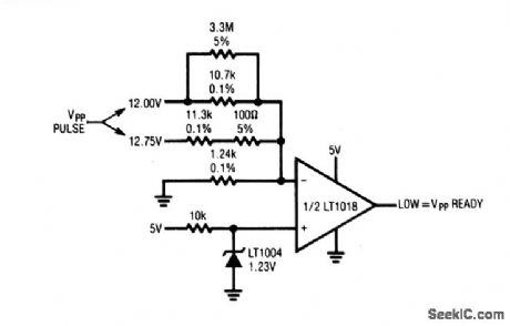
This circuit verifies that the VPP pulse generators (Figs. 6-49 and 6-50) are producing the correct output before pulsing begins. This is done by comparing the VPP output against the LT1004 reference. The LT1016 output goes low if the VPP output is correct. The resistor values shown allow for possible variations in VPP voltage because of component-tolerance stack-up. The output of the VPP generator should be set within 0.4% of nominal value when using this circuit. This can be done by trimming, or using 0.05% resistors in place of the 0.1% units specified.
Reprinted Url Of This Article:
http://www.seekic.com/circuit_diagram/Basic_Circuit/VSUBPP_SUB_handshake_circuit.html
Print this Page | Comments | Reading(3)

Article Categories
power supply circuit
Amplifier Circuit
Basic Circuit
LED and Light Circuit
Sensor Circuit
Signal Processing
Electrical Equipment Circuit
Control Circuit
Remote Control Circuit
A/D-D/A Converter Circuit
Audio Circuit
Measuring and Test Circuit
Communication Circuit
Computer-Related Circuit
555 Circuit
Automotive Circuit
Repairing Circuit
Code: