Basic Circuit
VOX__FOR_SSB
Published:2009/7/13 21:20:00 Author:May | From:SeekIC

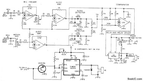
Uses LM3900 quad Norton opamp and NE555 timer operating from single supply. U1A and U1B amplify microphone signal. U1C amplifies audio sample obtained from station loudspeaker. Outputs of both amplifiers are converted to varying DC voltages by rectifiers in detector stages. Rectifier outputs are summed resistively by R6 and R7 for application to inverting input of voltage comparator U1D. Positive microphone signal drives comparator output low and triggers NE555, which in turn energizes 12-V relay K1 after delay set at about 10 ms by R8 to avoid losing first syllable. Same delay applies to relay dropout, to hold relay closed between words. If K1 drops out for fraction of second at end of timing cycle even though audio is present, add 2N5139 transistor to NE555 input as shown.-D. A. Blakeslee, A VOX for a Very Small Box, QST, March 1976, p 24-26.
Reprinted Url Of This Article:
http://www.seekic.com/circuit_diagram/Basic_Circuit/VOX__FOR_SSB.html
Print this Page | Comments | Reading(3)

Article Categories
power supply circuit
Amplifier Circuit
Basic Circuit
LED and Light Circuit
Sensor Circuit
Signal Processing
Electrical Equipment Circuit
Control Circuit
Remote Control Circuit
A/D-D/A Converter Circuit
Audio Circuit
Measuring and Test Circuit
Communication Circuit
Computer-Related Circuit
555 Circuit
Automotive Circuit
Repairing Circuit
Code: