Basic Circuit
VOLTAGE_DOUBLERS
Published:2009/7/11 4:52:00 Author:May | From:SeekIC

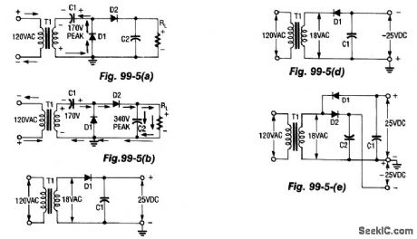
During the first half-cycle (Fig. 99-5(a)), D1 conducts, D2 cuts off, C1 charges to 170 V peak, and C2 discharges through RL For the second half-cycle (Fig. 99-5(b)), the input polarity is reversed, and both the input and C1 are in series, which produces 340 V (peak). Now, D1 cuts off, while D2 conducts, and the current divides between C2 and RL; the cycle then repeats. Two Half-Wave Rectifiers, one with a positive output (Fig. 99-5(c)) and one negative (Fig. 99-5(d)), combine to make a full-wave voltage doubler (Fig. 99-5(e)).
Reprinted Url Of This Article:
http://www.seekic.com/circuit_diagram/Basic_Circuit/VOLTAGE_DOUBLERS.html
Print this Page | Comments | Reading(3)

Article Categories
power supply circuit
Amplifier Circuit
Basic Circuit
LED and Light Circuit
Sensor Circuit
Signal Processing
Electrical Equipment Circuit
Control Circuit
Remote Control Circuit
A/D-D/A Converter Circuit
Audio Circuit
Measuring and Test Circuit
Communication Circuit
Computer-Related Circuit
555 Circuit
Automotive Circuit
Repairing Circuit
Code: