Basic Circuit
VISIBLE_RED_CONTINUOUS_LASER_GUN
Published:2009/7/7 21:09:00 Author:May | From:SeekIC


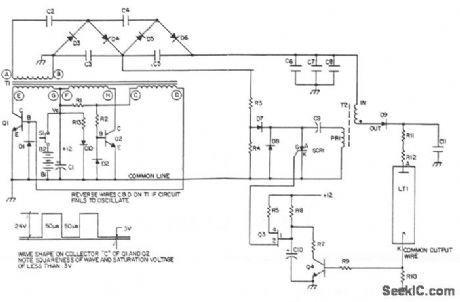
Q1 and Q2 switch the primary windings of transformer T1 via a square wave at a frequency determined by its magnetic properties. Diodes Dl and D2 provide base return paths for the feedback current of Q1 and Q2. The output winding of T1 is connected to a multiple section voltage multiplier. That multiplier consists of capacitors C1 through C5 and diodes D3 through D6. Resistors R3 and R4 divide the 800 V taken off at the junction of C3, and C5 for charging the dump capacitor C9 in the ignitor circuit. The ignitor, consisting of the T2 pulse transformer and capacitor discharge circuitry, provides the high-voltage dc pulse to ignite the laser the SCR1 dumping the energy of capacitor C9 into the primary of T2. The high-voltage pulses in capacitor C11 through rectifier diode D9. When C11 is charged to a LT1, ignition takes place and a current now flows that is sufficient to sustain itself at the lower voltage output of the voltage multiplier section. The path for this sustaining current is through the secondary of T2 and ballast resistors R11 and R12. The ignitor circuit is now deactivated by the clamping of Q3 emitter via Q4 being turned on by the voltage drop occurring across R10. This voltage drop will only occur when the laser tube is ignited and causes the SCR1 to cease firing; otherwise, the ignitor circuit would continue to operate, unnecessarily drawing on the limited power available.
Reprinted Url Of This Article:
http://www.seekic.com/circuit_diagram/Basic_Circuit/VISIBLE_RED_CONTINUOUS_LASER_GUN.html
Print this Page | Comments | Reading(3)

Article Categories
power supply circuit
Amplifier Circuit
Basic Circuit
LED and Light Circuit
Sensor Circuit
Signal Processing
Electrical Equipment Circuit
Control Circuit
Remote Control Circuit
A/D-D/A Converter Circuit
Audio Circuit
Measuring and Test Circuit
Communication Circuit
Computer-Related Circuit
555 Circuit
Automotive Circuit
Repairing Circuit
Code: