Basic Circuit
VERY_SHORT_PULSE_WIDTH_MEASURER
Published:2009/7/7 23:06:00 Author:May | From:SeekIC

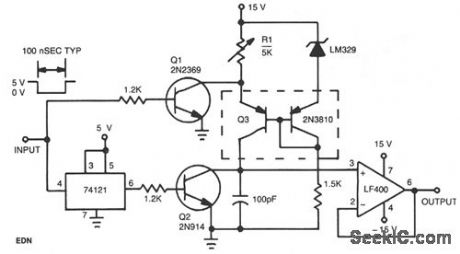
This circuit operates by charging a small capacitor from a constant-current source when the pulse to be measured is present. Dual pnp transistor Q3 is the current source; its output current equals the LM329 reference voltage divided by the resistance of potentiometer R1. When the input is high with no pulse present, Q1 keeps the current source turned off. When the pulse begins and the input decreases, Q1 turns off and the monostable multivibrator generates a short pulse. The pulse from the multivibrator turns on Q2, removing any residual charge from the 100-pF capacitor. Q2 then turns off, and the capacitor begins to charge linearly from the current source. When the input pulse ends, the current source turns off, and the voltage on the capacitor is proportional to the pulse width.
Reprinted Url Of This Article:
http://www.seekic.com/circuit_diagram/Basic_Circuit/VERY_SHORT_PULSE_WIDTH_MEASURER.html
Print this Page | Comments | Reading(3)

Article Categories
power supply circuit
Amplifier Circuit
Basic Circuit
LED and Light Circuit
Sensor Circuit
Signal Processing
Electrical Equipment Circuit
Control Circuit
Remote Control Circuit
A/D-D/A Converter Circuit
Audio Circuit
Measuring and Test Circuit
Communication Circuit
Computer-Related Circuit
555 Circuit
Automotive Circuit
Repairing Circuit
Code: