Basic Circuit
UJT_MONO
Published:2009/7/1 20:23:00 Author:May | From:SeekIC

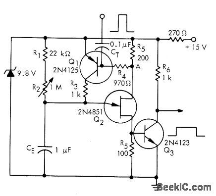
UJT Q2 is normally on, with its emitter saturation current supplied by transistor Q1 which is also on. Application of positive trigger pulse to base of a, turns both off to start timing cycle. CE starts charging each time from saturation voltage of UJT. When capacitor voltage becomes high enough to fire UJT, Q1 turns on and supplies emitter current required to keep UJT on. Output transistor a, delivers pulse having duration related to value used for CE.- Unijunction Transistor Timers and Oscillators, Motorola, Phoenix, AZ, 1974, AN-294 p 5.
Reprinted Url Of This Article:
http://www.seekic.com/circuit_diagram/Basic_Circuit/UJT_MONO.html
Print this Page | Comments | Reading(3)

Article Categories
power supply circuit
Amplifier Circuit
Basic Circuit
LED and Light Circuit
Sensor Circuit
Signal Processing
Electrical Equipment Circuit
Control Circuit
Remote Control Circuit
A/D-D/A Converter Circuit
Audio Circuit
Measuring and Test Circuit
Communication Circuit
Computer-Related Circuit
555 Circuit
Automotive Circuit
Repairing Circuit
Code: