Basic Circuit
Typical_testing_troubleshooting_application_of_probe_and_pulser
Published:2009/7/23 21:16:00 Author:Jessie | From:SeekIC

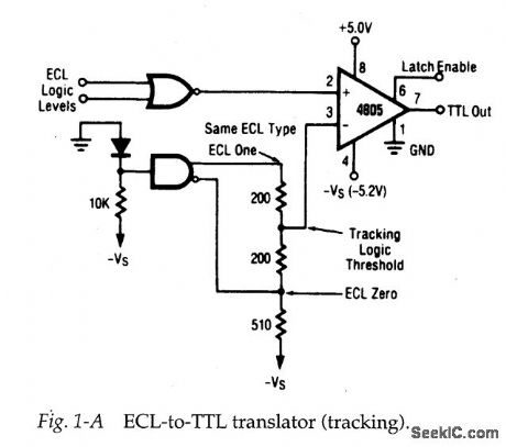
A circuit (such as Fig. 1-A) can be tested by applying a pulse at the input and monitoring the output. This can be done with a pulser (or signal generator) at the in-put and a probe (or scope) at the output. For example, pulses with ECL levels can be applied at the ECL-gate input and TTL pulses can be monitored at the output.If TTL pulses are absent at pin 7 of the 4805 comparator, check for pulses at pins 2 and 3. This procedure will isolate the problem to the gate or to the comparator.
Reprinted Url Of This Article:
http://www.seekic.com/circuit_diagram/Basic_Circuit/Typical_testing_troubleshooting_application_of_probe_and_pulser.html
Print this Page | Comments | Reading(3)

Article Categories
power supply circuit
Amplifier Circuit
Basic Circuit
LED and Light Circuit
Sensor Circuit
Signal Processing
Electrical Equipment Circuit
Control Circuit
Remote Control Circuit
A/D-D/A Converter Circuit
Audio Circuit
Measuring and Test Circuit
Communication Circuit
Computer-Related Circuit
555 Circuit
Automotive Circuit
Repairing Circuit
Code: