Basic Circuit
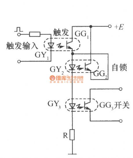
The switching circuit 1 with self-locking ( self-maintaining ) function
Published:2012/9/27 21:55:00 Author:Ecco | Keyword: switching , self-locking , self-maintaining function | From:SeekIC

The 3 optical couplers in Figure respectively play the role of the trigger, self-locking and switching. When a start trigger signal is applied to the GY , GG1 gets conduction, then there is current flowing through GY2 and GY3 to turn on GG2 and OG3. When the trigger signal disappears, GY1 does not emit light, then GG1 is cutoff, but at this time, the GG2 has been turned on, and the current of GY2 and GY3 is provided by GG2 passage, GG3 continues to maintain the conductive state, it is equivalent that the switch is still turned on until the power supply voltage E disappears in order to make the circuit restitution.
Reprinted Url Of This Article:
http://www.seekic.com/circuit_diagram/Basic_Circuit/The_switching_circuit_1_with_self_locking__self_maintaining__function.html
Print this Page | Comments | Reading(3)

Article Categories
power supply circuit
Amplifier Circuit
Basic Circuit
LED and Light Circuit
Sensor Circuit
Signal Processing
Electrical Equipment Circuit
Control Circuit
Remote Control Circuit
A/D-D/A Converter Circuit
Audio Circuit
Measuring and Test Circuit
Communication Circuit
Computer-Related Circuit
555 Circuit
Automotive Circuit
Repairing Circuit
Code: