Basic Circuit
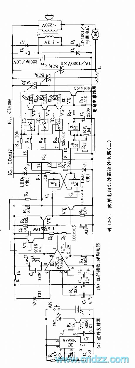
The infrared remote control circuit of 888 domestic fans(2)
Published:2011/5/30 22:19:00 Author:Borg | Keyword: remote control, 888 domestic fans | From:SeekIC

The model of infrared receiving pipe is coupled with the emitting pipe, the selection of wave length and light power should be noticed. IC1 is fixed with the special infrared receiving chip μPC1373 of color TV remote controls, when L and C4 circuits are modulated at the central frequency of 38kHz, an infrared pulse signal is received, and after magnification, detection and rectification by IC1, a low-LEV signal is output, then VT2 is blocked, and the high LEV signal of c pole is added to the input terminal of IC3 clock, then the clock starts to count, and Q1(2-pin) generates a high LEV pulse, the electric IC4-a and VT5 are conducting.
Reprinted Url Of This Article:
http://www.seekic.com/circuit_diagram/Basic_Circuit/The_infrared_remote_control_circuit_of_888_domestic_fans2.html
Print this Page | Comments | Reading(3)

Article Categories
power supply circuit
Amplifier Circuit
Basic Circuit
LED and Light Circuit
Sensor Circuit
Signal Processing
Electrical Equipment Circuit
Control Circuit
Remote Control Circuit
A/D-D/A Converter Circuit
Audio Circuit
Measuring and Test Circuit
Communication Circuit
Computer-Related Circuit
555 Circuit
Automotive Circuit
Repairing Circuit
Code: