Basic Circuit
The e-control circuit of the heat release electric sensor
Published:2011/7/14 6:31:00 Author:Borg | Keyword: e-control circuit, electric sensor | From:SeekIC
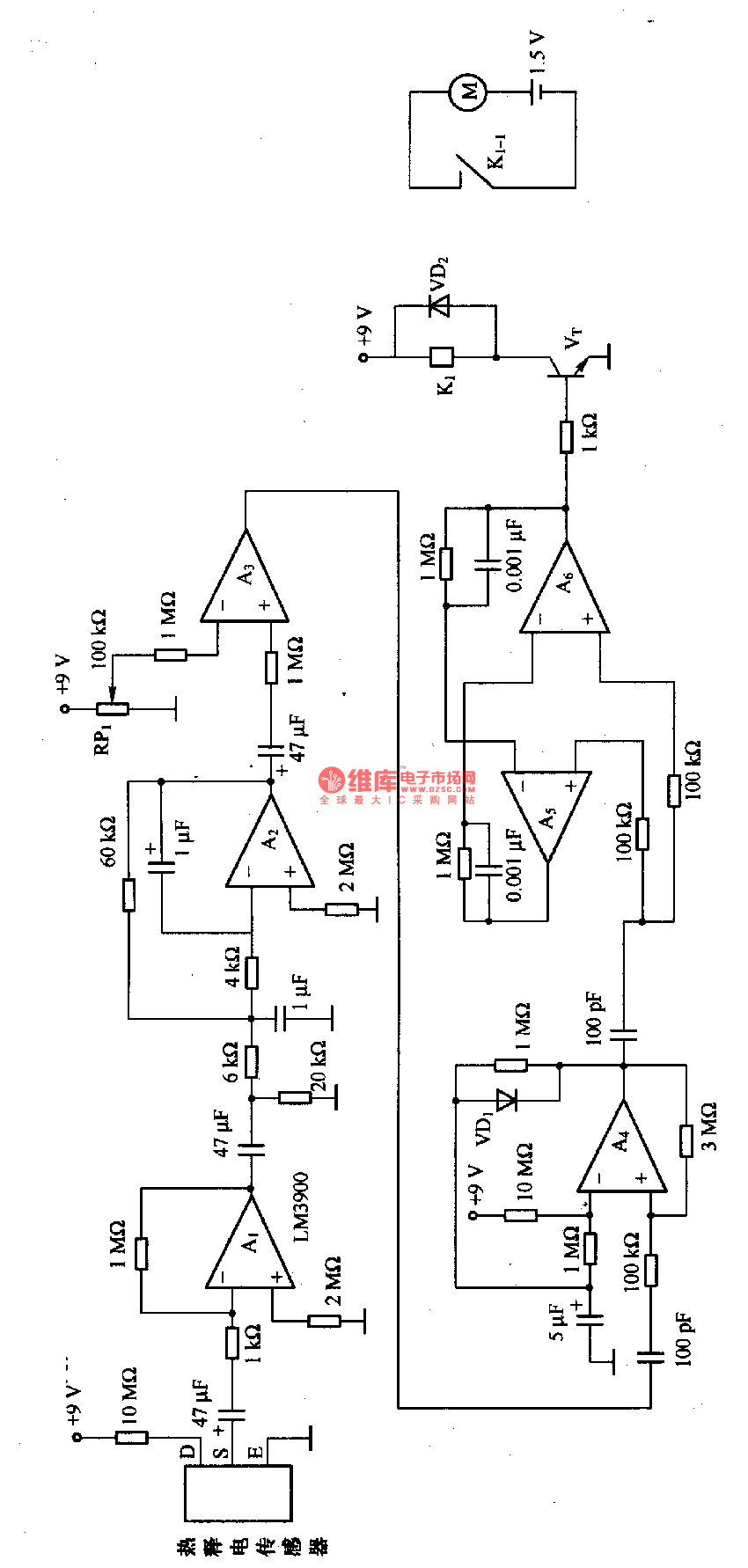
This is the e-control circuit of the heat release electric sensor. In the circuit, A1 is the amplifier circuit whose gain is 60dB, which amplifies the weak signal of the heat release sensor; A2 is the active filter whose block frequency is about 10Hz, which is used to filter the noise and wave; A3 is the comparator circuit, whose comparing value is set by RP1, A3 outputs the constant LEV signal; A4 is the single stable multiple resonance oscillator, which is used to make sure the circuit only reacts tothe signal of one sensor within a certain time when there are more than one heat release sensors.
Reprinted Url Of This Article:
http://www.seekic.com/circuit_diagram/Basic_Circuit/The_e_control_circuit_of_the_heat_release_electric_sensor.html
Print this Page | Comments | Reading(3)

Article Categories
power supply circuit
Amplifier Circuit
Basic Circuit
LED and Light Circuit
Sensor Circuit
Signal Processing
Electrical Equipment Circuit
Control Circuit
Remote Control Circuit
A/D-D/A Converter Circuit
Audio Circuit
Measuring and Test Circuit
Communication Circuit
Computer-Related Circuit
555 Circuit
Automotive Circuit
Repairing Circuit
Code: