Basic Circuit
TWO_WIRE_INTERCOM
Published:2009/7/9 22:06:00 Author:May | From:SeekIC

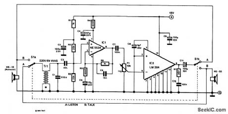
The design consists of an amplifier, a double-pole changeover switch and two loudspeakers:one forthe master station and one for the slave.More than one slave unit can be used,but each reqtures an additional changeover switch.
The power amplifier is a Type LM384,which can provide almost 2 W output at a supply voltage of 15V. Pins 3,4,5,10,11,and 12 are connected to ground and at the same time afford some coolling of thedevice,Because of that,the IC should not be fitted in a socket,but be soldered direct to the circuit board.
The LM384 processes signals with respect to earth so that an asymmetnc supply is sufficient.Theamplification has been set internally to×50(34 dB),The IC’s supply line is decoupled by C9.
To ensure adequate itiput sensitivity,a preamplifier,IC1,IS provided,which has an amplification of 11(21 dB).Because this stage IS intended for speech only, its bandwidth is limited to 160 Hz to 10 kHz.Divider R2/R3 at the input of the op amp is decoupled by C3.
Special loudspeakers that can also serve as microphones are readily available:in the prototype,MS-55units from Monacor were used,but a number of other makes will do Just db well.The bandwidth of the MS-55 (used db loudspeaker)extends from 150 Hz to 20 kHz and (used as a microphone)from 20 Hz to 20kHz,The MS-55 can handle up to 5-W output.To ensure satisfactory operation,particularly as a microphone,the loudspeaker must be fitted In a closed box.
Although it is advantageous for the microphone to have a low internal resistance,it is necessary for a transformer to be used at the input ofthe circuit,This has, however,the advantage that long cables canbe used.The present circuit uses a standard mains transformer instead of a special microphone trans-former. For this purpose,the secondary(6V) winding is connected to the microphone The microphone impedance is thereby magnified from about 8 Ω to around 10 kΩ.The power handling of thetransformer is quite high to ensure that signal losses in the primary winding are kept at a minimum. Capac-itor C1 suppresses HF interference.
If the mains transformer and the microphone transformer are housed in the same enclosure, some trial and error and screening are necessary to eliminate hum. The microphone transformer itself might cause hum in the remainder of the circuit. In that case, the preamp stage must also be screened.
In the prototype, the speech bandwidth was limited from 400 Hz to 4 kHz and this proved perfectly acceptable for good speech transfer. Most of the current drawn by the circuit flows through the power amplifier. At worst, this is 210 mA (680 mA peak), when the amplifier delivers 1.8-W output. The LM384 can deliver a power of up to 5 W. The supply voltage should then be raised to 22 V and a heatsm for the device will be necessary.
Reprinted Url Of This Article:
http://www.seekic.com/circuit_diagram/Basic_Circuit/TWO_WIRE_INTERCOM.html
Print this Page | Comments | Reading(3)

Article Categories
power supply circuit
Amplifier Circuit
Basic Circuit
LED and Light Circuit
Sensor Circuit
Signal Processing
Electrical Equipment Circuit
Control Circuit
Remote Control Circuit
A/D-D/A Converter Circuit
Audio Circuit
Measuring and Test Circuit
Communication Circuit
Computer-Related Circuit
555 Circuit
Automotive Circuit
Repairing Circuit
Code: