Basic Circuit
TWO_GATE_SCHMlTT
Published:2009/7/2 4:33:00 Author:May | From:SeekIC


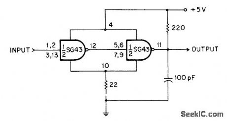
TTL inverter gates are connected in series, with small feedback resistorin common ground lead, so gates are always in opposing logic states. Resulting constqnt voltage drop across 22-ohm resistor produces constant offset voltage that is corrected by 220-ohm resistor at output terminal. With values shown, positive-going threshold is 2.4 V and negative-going threshold is 2 V.-C. J. Ulrick, Schmitt Tdgger Uses Two Logic Gates, EEE Magazine, Dee. 1970, p 54.
Reprinted Url Of This Article:
http://www.seekic.com/circuit_diagram/Basic_Circuit/TWO_GATE_SCHMlTT.html
Print this Page | Comments | Reading(3)

Article Categories
power supply circuit
Amplifier Circuit
Basic Circuit
LED and Light Circuit
Sensor Circuit
Signal Processing
Electrical Equipment Circuit
Control Circuit
Remote Control Circuit
A/D-D/A Converter Circuit
Audio Circuit
Measuring and Test Circuit
Communication Circuit
Computer-Related Circuit
555 Circuit
Automotive Circuit
Repairing Circuit
Code: