Basic Circuit
TWO_CELL_TO_5_V_BOOST_CONVERTER
Published:2009/7/13 2:43:00 Author:May | From:SeekIC

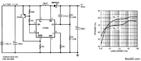
Extending the battery life of a portable device that spends most of its life time in standby mode is critical in two-cell applications. The standard LT1304 boost circuit requires two capacitors, one diode, and one inductor and provides 5 V at 200 mA from a two-cell battery with 80 percent typical efficiency. For improved efficiency at very light loads, the LT1304 switching regulator circuit shown achieves an efficiency of 50 percent at just 10 μA of load current. As indicated in the graph, high efficiency over a very wide range of load current is obtained by using the extra circuitry to control Burst Mode operation. The LT1304 is a micropower step-up dc-to-dc converter with an internal comparator that is operational in shutdown. The peak switch current limit can be set up to 1 A by the resistor at the ILIM input. In this circuit, it is set to 500 mA. The input voltage range extends down to 1.65 V, ensuring operation-even as the two-cell battery voltage drops during discharge. The on-board comparator shuts down the LT1304 micropower regulator when the output voltage is higher than the target 5-V output. In shutdown, the LT1304 consumes 10 μA of current, which is less than one-tenth of its active quiescent current of 120 μA. When the output voltage begins to droop below the target 5-V output, the comparator switches the LT1304 on again to recharge the output capacitor.
Reprinted Url Of This Article:
http://www.seekic.com/circuit_diagram/Basic_Circuit/TWO_CELL_TO_5_V_BOOST_CONVERTER.html
Print this Page | Comments | Reading(3)

Article Categories
power supply circuit
Amplifier Circuit
Basic Circuit
LED and Light Circuit
Sensor Circuit
Signal Processing
Electrical Equipment Circuit
Control Circuit
Remote Control Circuit
A/D-D/A Converter Circuit
Audio Circuit
Measuring and Test Circuit
Communication Circuit
Computer-Related Circuit
555 Circuit
Automotive Circuit
Repairing Circuit
Code: