Basic Circuit
TTL_COMPATIBLE_SCHMITT_TRIGGER
Published:2009/7/7 4:15:00 Author:May | From:SeekIC


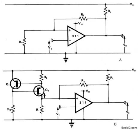
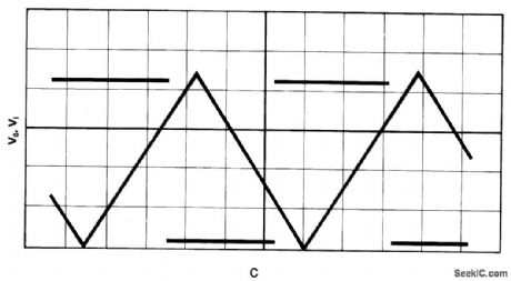
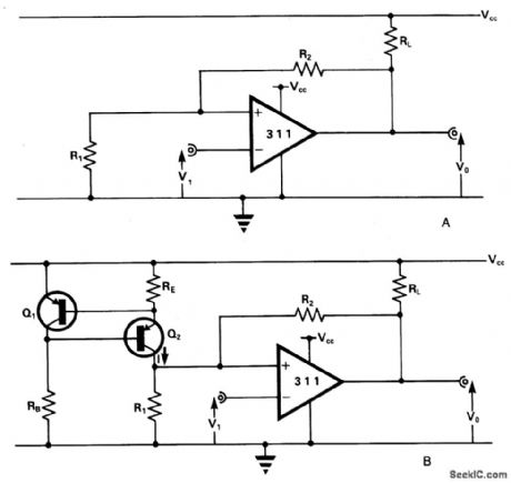
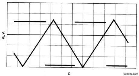
The comparator has an output pull-up resistor RL. and is connected up to operate as a Schmitt trigger using the single rail supply Vcc. The feedback resistors R1 and R2 give upper and lower threshold levels VT+ , VVVTW, respectively. VT+ , is easily set by suitable resistor selection but there is little independent choice of VT- because VT- cannot exceed VCE(SAT) In Fig. 15-13B current-source, comprising the transistors RE, Rg produces a current I~:(VEB/RE), VEB (~0.65 V) being the emitter-base voltage of Q1 and Q2. Fig. 15-13C shows the results of a practical test using the circuit of Fig.15-13B, and the following operating and component data: Vcc=5 V; RL = 1 K ohm; R1=R2=10 K ohm; RB=3.6 K ohm; RE=1K ohm + 10 K ohm pot; Q1=ZTX500; Q2 - ZTX500.
Reprinted Url Of This Article:
http://www.seekic.com/circuit_diagram/Basic_Circuit/TTL_COMPATIBLE_SCHMITT_TRIGGER.html
Print this Page | Comments | Reading(3)

Article Categories
power supply circuit
Amplifier Circuit
Basic Circuit
LED and Light Circuit
Sensor Circuit
Signal Processing
Electrical Equipment Circuit
Control Circuit
Remote Control Circuit
A/D-D/A Converter Circuit
Audio Circuit
Measuring and Test Circuit
Communication Circuit
Computer-Related Circuit
555 Circuit
Automotive Circuit
Repairing Circuit
Code: