Basic Circuit
TOUCHOMATIC
Published:2009/7/7 5:39:00 Author:May | From:SeekIC

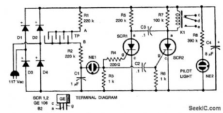
When someone touches the touchplate (TP), the resistance of his finger across points A and B is added in series to the combination of R1 and R2, the capacitor C2 begins to charge. When the voltage across C1 is finally sufficient to fire NE1, C1 will begin to discharge. When NE1 fires, it produces a short between its terminals. Since R3 is connected across C1, they are effectively in series after NE1 fires. A voltage spike will then be passed by C2 and this will act as a positive triggering pulse. The pulse is fed to both SCR gates: SCR2 conducts, there by closing relay K1. With a finger no longer on the touchplate, no more pulses are forthcoming because the C1 charge path is open.The next contact with the touchplate will produce a pulse which triggers SCR1. SCR2 is now off by capacitor C3 which was charged by current passing through R6 and SCR2.The firing of SCR1 in this way places a negative voltage across SCR2 which momentarily drops the relay current to a point below the holding current value of SCR2. (Holding current is the minimum current an SCR requires to remain in a conducting state once its gate voltage is removed.) With SCR2 turned off, the relay will open and SCR1 will turn off due to the large resistance in series with its anode. Starved in this way SCR1 turns off because of a forced lack of holding current.
Reprinted Url Of This Article:
http://www.seekic.com/circuit_diagram/Basic_Circuit/TOUCHOMATIC.html
Print this Page | Comments | Reading(3)

Article Categories
power supply circuit
Amplifier Circuit
Basic Circuit
LED and Light Circuit
Sensor Circuit
Signal Processing
Electrical Equipment Circuit
Control Circuit
Remote Control Circuit
A/D-D/A Converter Circuit
Audio Circuit
Measuring and Test Circuit
Communication Circuit
Computer-Related Circuit
555 Circuit
Automotive Circuit
Repairing Circuit
Code: