Basic Circuit
THREE_PHASE_CLOCK_FROM_AREFERENCE_CLOCK
Published:2009/7/6 5:35:00 Author:May | From:SeekIC

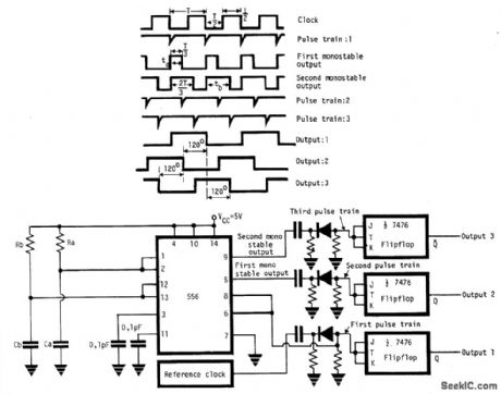
The circuit provides three square wave outputs with 120' of phase difference between each other. Reference clock frequency is twice that of the required frequency. This can be obtained from a crystal oscillator with a chain of dividers or by using LM555 in 50% duty cycle astable mode. If1/T is the frequency of the reference clock, the dual timer 556 is connected to give two mono-stable output pulses of duration T/3 and 2T/3. The first timer R and C value are adjusted so that ta 1.1RaCa = T/3 and the second timer R and C values so that tb = 1.1RbCb =2T/3. For triggering the two monostables a negative pulse train (1st) is derived from the reference clock with a differentiator and a clipper combination as shown. The three pulse trains trigger three JK flip flops giving three phase square wave outputs.
Reprinted Url Of This Article:
http://www.seekic.com/circuit_diagram/Basic_Circuit/THREE_PHASE_CLOCK_FROM_AREFERENCE_CLOCK.html
Print this Page | Comments | Reading(3)

Article Categories
power supply circuit
Amplifier Circuit
Basic Circuit
LED and Light Circuit
Sensor Circuit
Signal Processing
Electrical Equipment Circuit
Control Circuit
Remote Control Circuit
A/D-D/A Converter Circuit
Audio Circuit
Measuring and Test Circuit
Communication Circuit
Computer-Related Circuit
555 Circuit
Automotive Circuit
Repairing Circuit
Code: