Basic Circuit
THE_WAILING_SIREN
Published:2009/7/10 1:44:00 Author:May | From:SeekIC

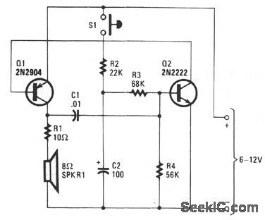
Transistors Q1 and Q2, with feedback provided via C1 from the collector of Q1 to the base of Q2, forms a voltage-controlled oscillator (VCO). Depending on the voltage applied to Q2's base, the VCO frequency ranges from around 60 Hz to 7.5 kHz. The instantaneous voltage applied to the base of Q2 is determined by the values of C2, R2, R3, and R4. When pushbutton switch S1 is closed, C2 charges fairly rapidly to the maximum supply voltage through R2, a 22-KΩ fixed resistor. That causes the siren sound to rise rapidly to its highest frequency. When the button is released, the capacitor discharges through R3 and R4 with a combined resistance of 124 KΩ, causing the siren sound to decay from a high-pitched wail to a low growl. If you want to experiment with the pitch of the sound at its highest frequency, try different values for C1. ncrease its value for lower notes, and decrease it for higher ones. Different values for R2 will change the attack time. A 100-KΩ resistor provides equal attack and decay times. The way you handle the pushbutton varies the effect.
Reprinted Url Of This Article:
http://www.seekic.com/circuit_diagram/Basic_Circuit/THE_WAILING_SIREN.html
Print this Page | Comments | Reading(3)

Article Categories
power supply circuit
Amplifier Circuit
Basic Circuit
LED and Light Circuit
Sensor Circuit
Signal Processing
Electrical Equipment Circuit
Control Circuit
Remote Control Circuit
A/D-D/A Converter Circuit
Audio Circuit
Measuring and Test Circuit
Communication Circuit
Computer-Related Circuit
555 Circuit
Automotive Circuit
Repairing Circuit
Code: