Basic Circuit
TAPE_RECORDER_INTERFACE
Published:2009/7/6 20:12:00 Author:May | From:SeekIC

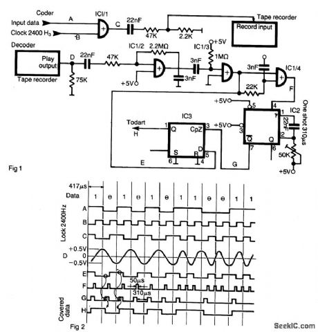
The interface allows data to be saved on an ordinary tape recorder at a speed of 2400 bit/s.The serial stream of data Fig. 1 (A) is coded with a clock of 2400 Hz (B), by means of XOR gate IC 1/1. Logical high and low appear as shown in Fig. 2 (C). These impulses are lowered in amplitude and feed into the record input of a low cost tape recorder.During the playback, pulses (D) are amplified with CMOS gate IC 1/2 connected as a linear amplifier, and providing a TTL level signal shown in (E). On both positive and negative transitions IC 1/4 forms short pulses as shown in (F) (approx. 50 ps) that triggers one shot IC2. A monostable one shot pulse width is adjusted to be 3/4 of bit length (310 pts). A change from high to low in a coded stream generates a low pulse width of one bit cell. The same is for change from low to high that generates a high pulse of the same width. During this pulse one shot latches the state of line E in D type flip-flop IC3 (G). When a stream consists of multiple ones or zeros, the one shot is retriggered before it comes to the end of the quasistable state and the state of the flip-flop remains unchanged. The original data stream is available at the output of the flip-flop (H). 280 the DUART that receives these pulses is programmed so that the receiver clock is 16 times the data rate (38.4 kHz).
Reprinted Url Of This Article:
http://www.seekic.com/circuit_diagram/Basic_Circuit/TAPE_RECORDER_INTERFACE.html
Print this Page | Comments | Reading(3)

Article Categories
power supply circuit
Amplifier Circuit
Basic Circuit
LED and Light Circuit
Sensor Circuit
Signal Processing
Electrical Equipment Circuit
Control Circuit
Remote Control Circuit
A/D-D/A Converter Circuit
Audio Circuit
Measuring and Test Circuit
Communication Circuit
Computer-Related Circuit
555 Circuit
Automotive Circuit
Repairing Circuit
Code: