Basic Circuit
Square_root_circuit
Published:2009/7/24 11:09:00 Author:Jessie | From:SeekIC

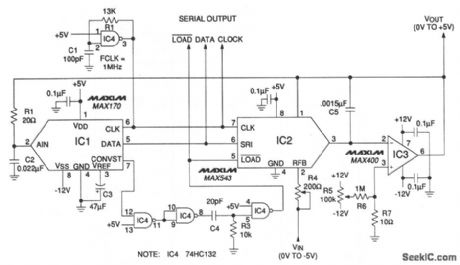
In this circuit, a 12-bit MAX543 DAC and a MAX170 A/D operate in the feedback loop of a single op amp to determine the square-root or a 0- to -5-V input signal. Both analog (VOUT) and digital outputs (serial DATA output) are provided. Accuracy surpasses 0.1% for -5-mV to 5-V inputs. The MAX543 squares the op-amp input, with an output that is proportional to IOUT=VREF(DAC code) +VIN. One DAC multiplying input is digital. The MAX170 A/D digitizes the op-amp output and transmits 12-bit data to the DAC. Consequently, the DAC VREF input and digital input carry the same value. The DAC output is then: IOUT=√5 ×√-VIN . Typical input/output examples are: VIN=-5.000 V, VOUT=+5.000 V; VIN=-0.5 mV, and VOUT=+50 mV. Maxim, 1992,Appications and Product Highlights, p. 8-14.
Reprinted Url Of This Article:
http://www.seekic.com/circuit_diagram/Basic_Circuit/Square_root_circuit.html
Print this Page | Comments | Reading(3)

Article Categories
power supply circuit
Amplifier Circuit
Basic Circuit
LED and Light Circuit
Sensor Circuit
Signal Processing
Electrical Equipment Circuit
Control Circuit
Remote Control Circuit
A/D-D/A Converter Circuit
Audio Circuit
Measuring and Test Circuit
Communication Circuit
Computer-Related Circuit
555 Circuit
Automotive Circuit
Repairing Circuit
Code: