Basic Circuit
Single_2nd_order_filter_section
Published:2009/7/24 12:59:00 Author:Jessie | From:SeekIC
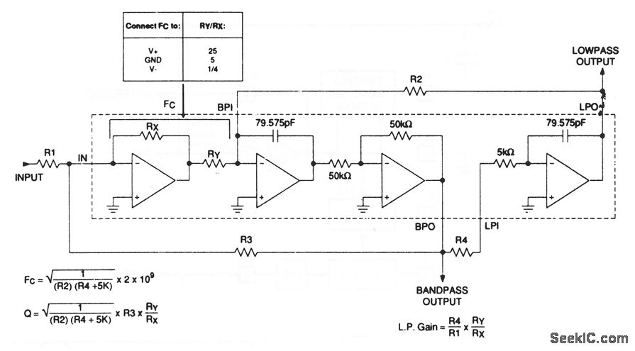
The MAX274/275 continuous-filter architecture uses a four-amplifier state-variable design. The on-chip capacitors and amplifiers, together with external resistors, form cascaded integrators with feedback to provide simultaneous low-pass and bandpass filtered outputs. The low-pass and bandpass frequencies, as well as filter Q, are determined by external resistor values, using the equations shown. No external capacitors are needed. On-chip capacitors are factory trimmed to provide better than 1% pole-frequency accuracy over the temperature range. ±1%-tolerance resistors provide ±2%-accurate pole frequencies. Accurate filter Qs can also be obtained by compensating for amplifier bandwidth limitation using the graphs that are provided on the data sheet. Maxim, 1992, Applications and Product Highlights, p. 7-3.
Reprinted Url Of This Article:
http://www.seekic.com/circuit_diagram/Basic_Circuit/Single_2nd_order_filter_section.html
Print this Page | Comments | Reading(3)

Article Categories
power supply circuit
Amplifier Circuit
Basic Circuit
LED and Light Circuit
Sensor Circuit
Signal Processing
Electrical Equipment Circuit
Control Circuit
Remote Control Circuit
A/D-D/A Converter Circuit
Audio Circuit
Measuring and Test Circuit
Communication Circuit
Computer-Related Circuit
555 Circuit
Automotive Circuit
Repairing Circuit
Code: