Basic Circuit
Sine wave inverter circuit diagram
Published:2014/3/17 21:29:00 Author:lynne | Keyword: Sine wave inverter circuit diagram, ICL7660, MAX1044 | From:SeekIC


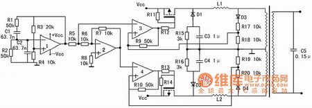
Existing inverter, well-sine wave output and output. High efficiency inverter square wave output, but are designed for the electrical sine wave power, the use is not always assured, although you can apply to many appliances, but some appliances do not apply, or electrical indicators up change. Sine wave output inverter no shortcomings in this area, but there is the disadvantage of low efficiency. Designed a highly efficient sine wave inverter, the circuit shown in Figure 1.
The circuit is powered by a 12V battery. First with a voltage doubler amplifier module times the pressure of supply. Can select ICL7660 or MAX1044. Op amp a 50Hz sine wave as a reference signal generated. 2 op amp as an inverter. 3 and op amp op amp as a comparator with hysteresis 4. In fact, the op amp 3 and switch a proportion of the switching power supply is constructed. Operational amplifier 4 and switch 2 also. Its switching frequency is unstable. In the op-amp output signal is positive phase, the op amp 3 and switch jobs. Then the output of op amp 2 is negative phase. Then the positive input of operational amplifier 4, the potential (fixed to 0) than the high potential of the negative input, the output of operational amplifier 4 is a constant, the switch is closed. In an op-amp output is negative phase, the opposite. This enables the two switches alternately work.
Below is a discussion about how the switch works. When the reference signal is less than the detection signal, that is the amplifier negative input terminal 3 or 4 signal is high a small value than the positive input signal, the comparator outputs 0, the switch opened, followed detection signal rapidly increased, when the detection signal higher than the reference value of a tiny signal, the comparator output 1, switch off. It should be noted here that, in the comparator circuit has a flip positive feedback, which is a hysteresis characteristic of the comparator. For example, under the reference signal is lower than the detection signal of the premise, as they continue to close the difference, at the moment they are equal, the reference signal detection signal immediately higher than a certain value. This certain value affect the switching frequency. The lower it is the greater frequency. Here choose it for the 0.1 ~ 0.2V.
C3, C4 role is to allow a high frequency current through the freewheeling switch, while the low-frequency impedance greater 50Hz signal. C5 by the equation: 50 = calculated. L is generally 70H, the production is best measured it. Thus C is about 0.15μ. The ratio of R4 and R3 should be strictly equal to 0.5, significantly larger waveform distortion, small start-up can not be, but rather a number of large, non-small. Maximum current switch is: I == 25A.
Click here for a more detailed discussion of selected values of L1, L2's. Equivalent to the load back to the input side of the transformer, the circuit of Figure 2.
Considering the switching frequency is much greater than 50Hz , the switch from on to off in the process , you can put a voltage transformer as a constant. The output of the power energy of the L : W = ∫ Uccdt = t
Ignore all the loss is not ideal , this energy should be equal to the load energy consumption . The average power of the formula : P == t
I hope when Ucc-U is close to a small value, the battery can be higher switching frequencies and to meet the requirements of the transformer. This a little value here take 0.5V, the frequency of taking 5kHz. When Ucc-U <0.5V, the switch will open a long time (which is relatively a ) . If you need the power of the maximum output power of 150W, then the load resistance is 322.7Ω, converted to the transformer input is : 0.48 Ω.
∴ instantaneous load power at this time is : P == 276W∴ P = × = 276∴ L = 2.2μH
L value can be seen in small disadvantage for the switch , and the output is clipping . You can increase the production of L values, but the maximum output power will be reduced. The best way to solve this problem is to use 16V power supply , the transformer is also used 8.5V (peak to 12V), and the peak for the reference signal of 12V , but this time the need to change the circuit .
Reprinted Url Of This Article:
http://www.seekic.com/circuit_diagram/Basic_Circuit/Sine_wave_inverter_circuit_diagram.html
Print this Page | Comments | Reading(3)

Article Categories
power supply circuit
Amplifier Circuit
Basic Circuit
LED and Light Circuit
Sensor Circuit
Signal Processing
Electrical Equipment Circuit
Control Circuit
Remote Control Circuit
A/D-D/A Converter Circuit
Audio Circuit
Measuring and Test Circuit
Communication Circuit
Computer-Related Circuit
555 Circuit
Automotive Circuit
Repairing Circuit
Code: